

Diaphragm pump and cooling system with the diaphragm pump
a diaphragm pump and diaphragm technology, which is applied in the direction of machines/engines, flexible member pumps, and positive displacement liquid engines, etc., can solve the problems of increasing the power consumption of electronic parts such as cpu, and reducing the flow rate of liquid through the flow passage. , to achieve the effect of increasing the pump efficiency, reducing the thickness, and increasing the cooling efficiency
- Summary
- Abstract
- Description
- Claims
- Application Information
AI Technical Summary
Benefits of technology
Problems solved by technology
Method used
Image

Examples
first embodiment
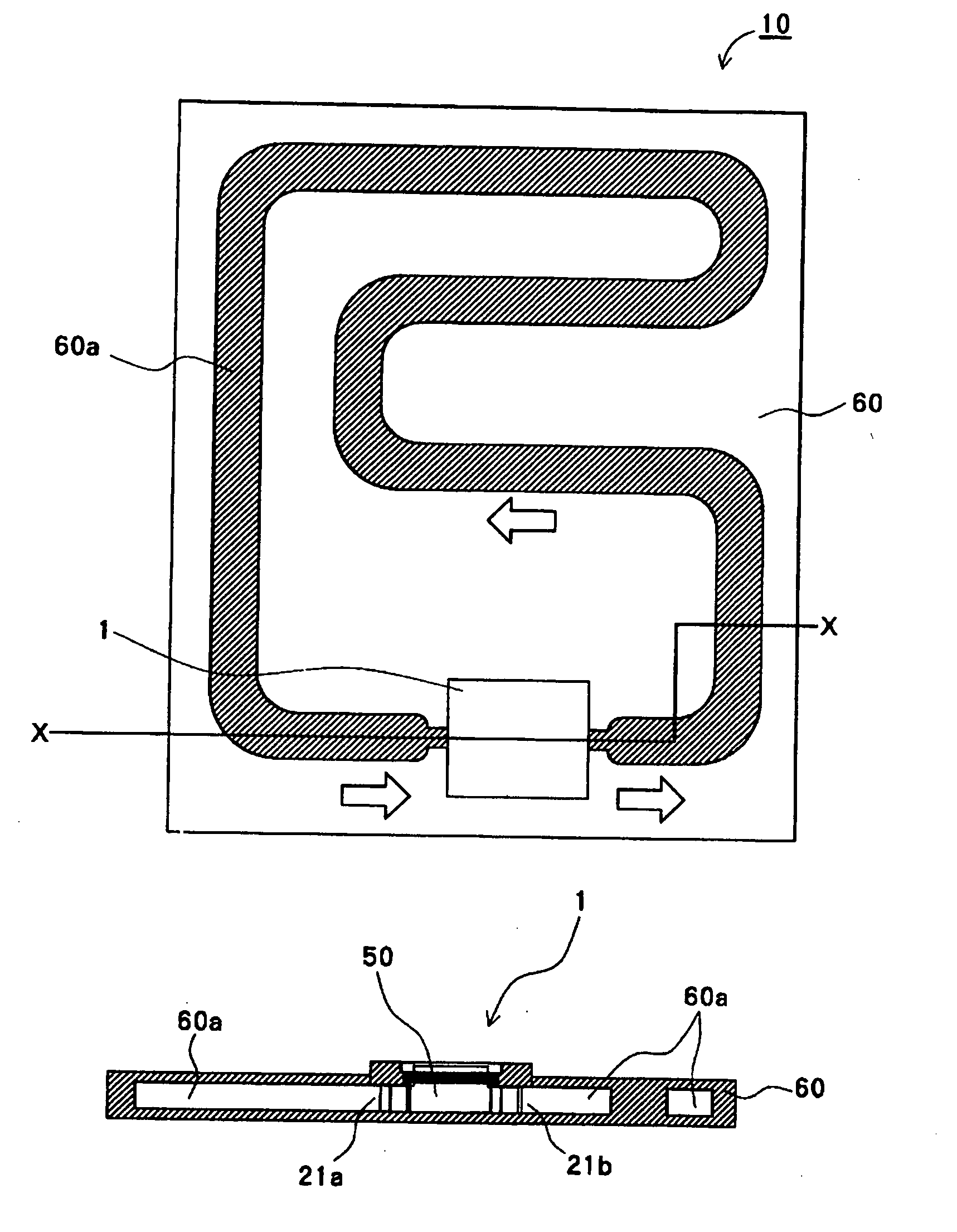
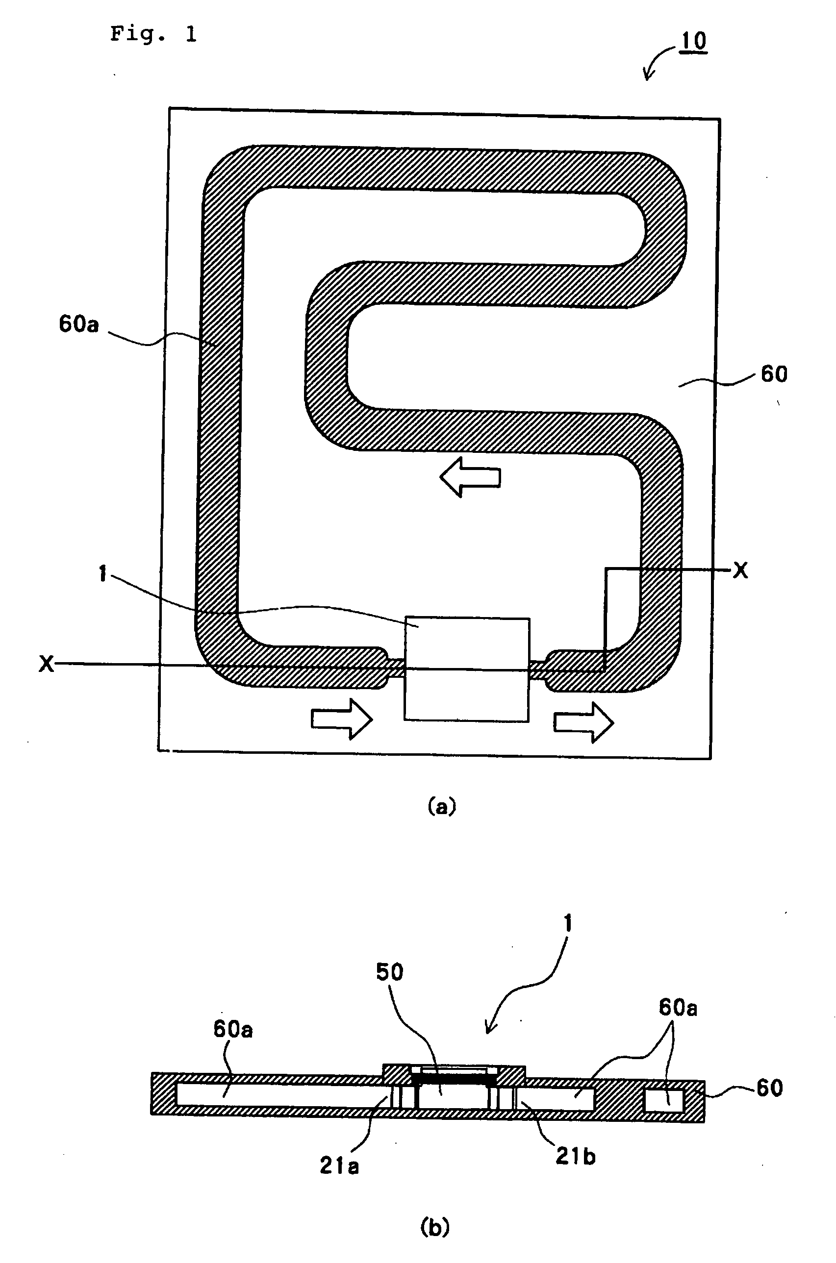
[0038]FIG. 1 shows schematic views of a cooling system provided with a piezoelectric pump of a first embodiment according to the present invention, FIG. 1(a) is a plan view showing a liquid passage in the cooling system, and FIG. 1(b) is a sectional view along line X-X in FIG. 1(a).
[0039] Cooling system 10 shown in FIG. 1 is a water-cooled cooling apparatus preferably used for providing cooling for electronic equipment, such as a portable personal computer. Cooling system 10 is roughly provided with flow passage unit 60 in which circulation flow passage 60a is formed and piezoelectric pump 1 connected to flow passage unit 60 and is used to circulate liquid in the flow passage. Flow passage unit 60 and piezoelectric pump 1 provide a closed-structure flow passage. Inside the flow passage, liquid to be circulated is filled up.
[0040] In flow passage unit 60, circulation flow passage 60a is formed in a predetermined pattern. There are no particular limitations to the sectional shape of...
second embodiment
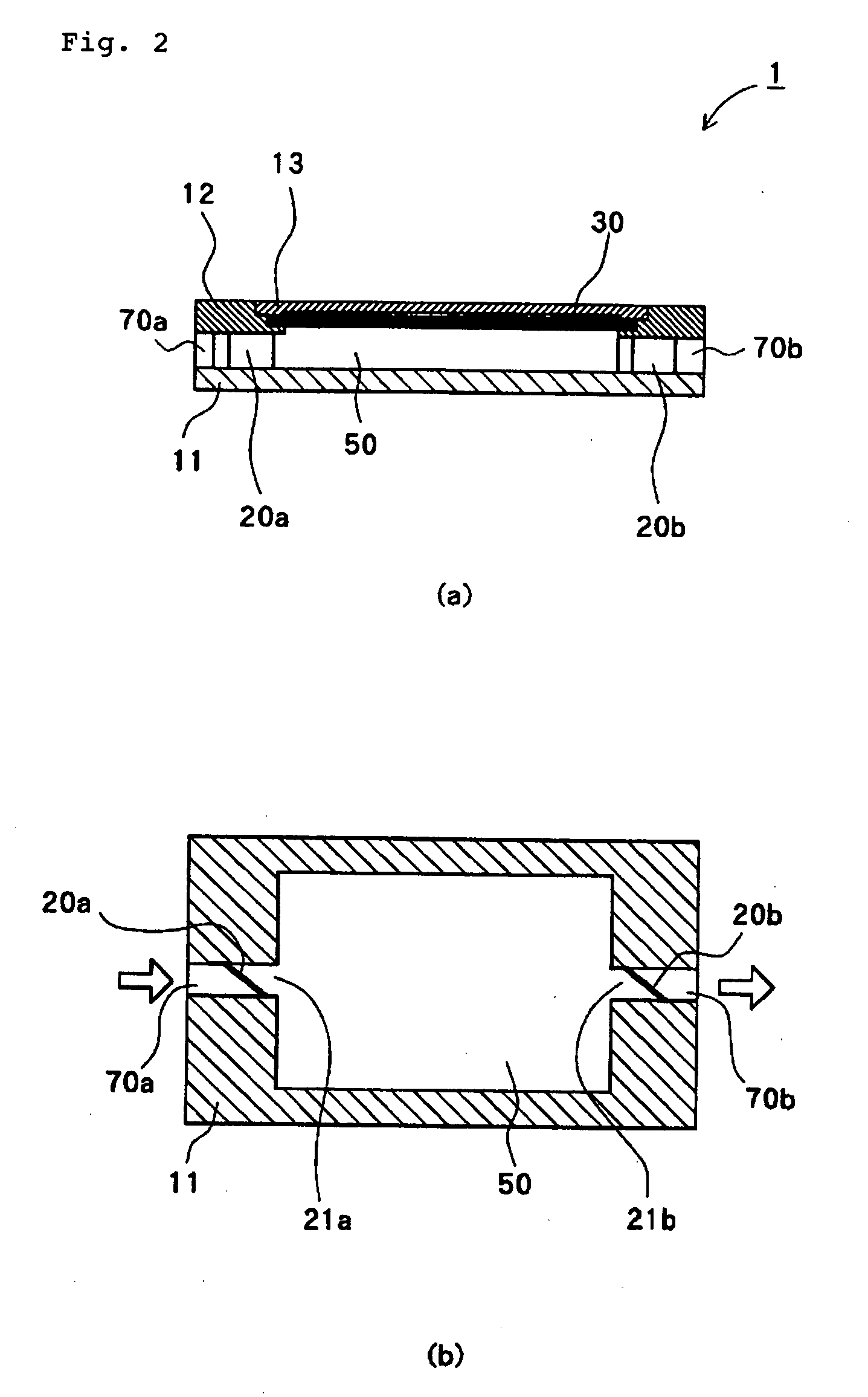
[0057] In the first embodiment, the pressure chamber is formed in a rectangular parallelepiped shape, however, the pressure chamber may be formed so that the cross-sectional area of the pressure chamber is gradually varied in order to reduce the resistance of the liquid.
[0058]FIG. 3 shows the piezoelectric pump of the second embodiment according to the present invention. Piezoelectric pump 2 shown in FIG. 3 is formed so that pressure chamber 50′ is formed in a streamlined shape. On peripheral walls of pressure chamber 50′, structural parts (retuning grooves 11a) for accelerating the flow of the liquid are arranged. The other structures are similar those of piezoelectric pump 1 shown in FIG. 2, and the same numeral references are applied to the structural parts having the same functions and explanations thereof are omitted.
[0059] Pressure chamber 50′, as shown in FIG. 3(b), is provided with peripheral wall surface 11e in an approximate streamlined shape viewed from the upper surfac...
third embodiment
[0068] Generally, a closed-structure flow passage in cooling system 10 shown in FIG. 1 is filled up with the liquid so that no bubbles remain. However, for example, there is a case in which dissolved oxygen is changed into bubbles and the bubbles are mixed into the liquid. In a piezoelectric pump, the existence of bubbles inside the flow passage causes a reduction in pump efficiency. Further, the existence of bubbles inside the closed-structure flow passage causes a reduction in cooling efficiency of cooling system 10.
[0069] So, in order to further improve pump efficiency, in addition to the two above-mentioned embodiments, a piezoelectric pump may be provided with means for collecting bubbles mixed in the liquid.
[0070] Respective piezoelectric pumps 3, 3′, 3″ shown in FIG. 7 to FIG. 9 are provided with gaseous chambers 35, 35′, 35″. FIGS. 7(a), 8(a) and 9(a) are lateral section views of piezoelectric pumps 3, 3′, 3″, and FIGS. 7(b), 8(b) and 9(b) are longitudinal section views of...
PUM
 Abstract
Description
Claims
Application Information