Real-time head tracking system for computer games and other applications

a head tracking and computer game technology, applied in the field of computer vision systems, can solve the problems of inability to accurately predict the shape of the object, the effect of reducing the cost of correlation operation, and the relatively high amount of computation for mapping from the 3d model to the image, etc., and achieve the effect of computational efficiency

Inactive Publication Date: 2007-03-22
JOLLY SEVEN SERIES 70 OF ALLIED SECURITY TRUST I
View PDF23 Cites 30 Cited by
  • Summary
  • Abstract
  • Description
  • Claims
  • Application Information

AI Technical Summary

Benefits of technology

[0010] This invention resides in a real-time computer vision system capable of tracking moving objects in a scene. Unlike current search and locate algorithms, the subject algorithm uses a target location technique which does not involve search. The system tracks objects based on the color, motion and shape of the object in the image. The tracking algorithm uses a unique color matching technique which uses minimal computation. This color matching function is used to compute three measures of the target's probable location based on the target color, shape and motion. It then computes the most probable location of the target using a weighting technique. These techniques make the invention very computationally efficient also makes it robust to noise, occlusion and rapid motion of the target.

Problems solved by technology

The correlation operation is computationally expensive and usually is performed using specialized hardware.
The disadvantage of such model based tracking methods is the relatively high amount of computation for the mapping from the 3D model to the image.
These techniques are faster than correlation methods but are less robust to changing shape and temporary occlusion by similarly colored objects in the scene.
Each of the modules involved places a large computational load on the computer.
The method also involves a high amount of computation.
The method is computationally expensive correlation is done via hardware.
The amount of computation involved is immense.

Method used


Image

  • Real-time head tracking system for computer games and other applications
  • Real-time head tracking system for computer games and other applications
  • Real-time head tracking system for computer games and other applications

Examples


Embodiment Construction

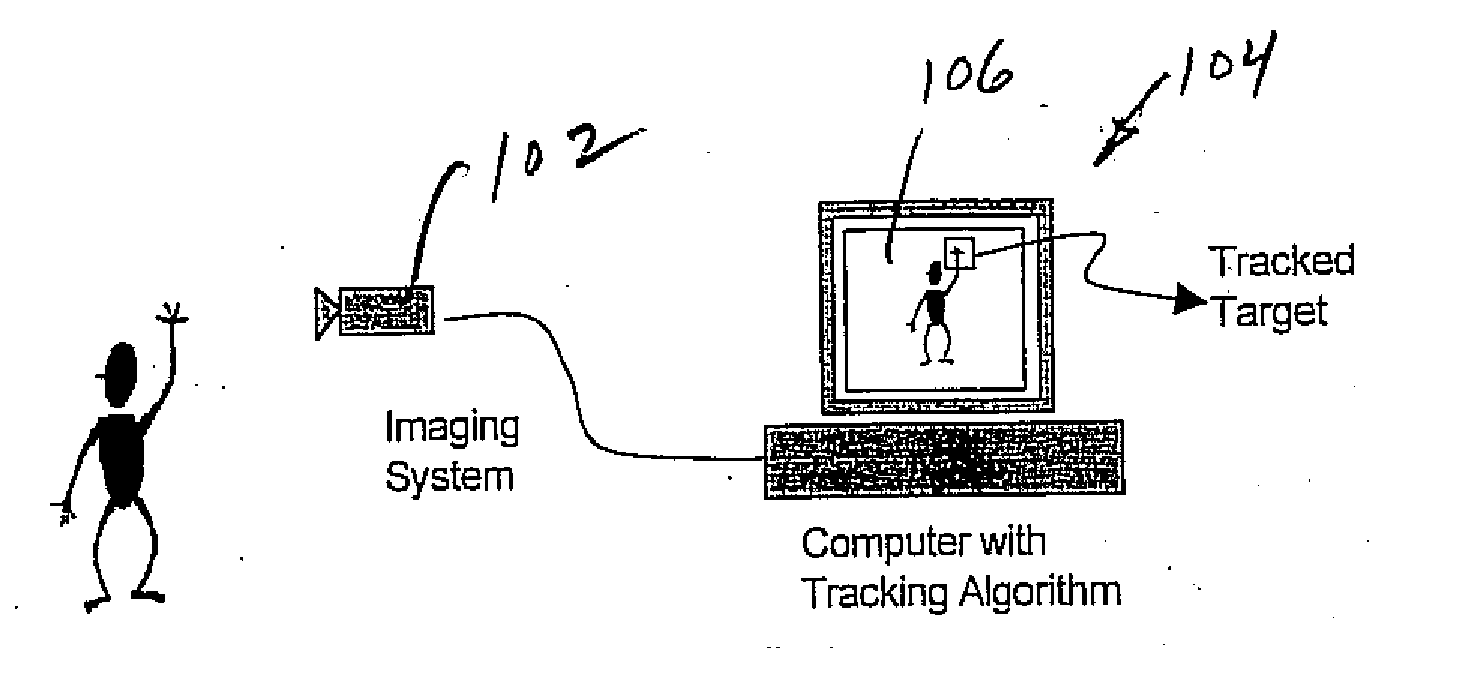
[0019] A schematic of the system is shown in FIG. 1. The imaging hardware includes a color camera 102 and a digitizer. The sequence of images of the scene is then fed to a computer 104 which runs tracking software according to the invention. The tracking algorithm is independent of the imaging system hardware. The tracking system has a graphical user interface (GUI) to initialize the target and show the tracking result on the screen 106.

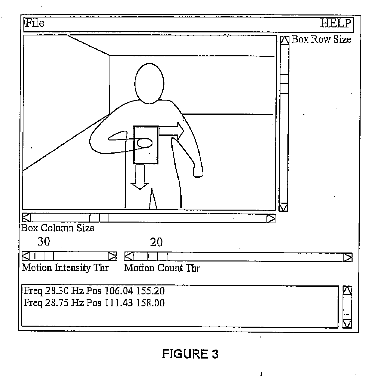
[0020] The GUI for the ROTS displays a live color image from the camera on the computer screen. The user can initialize the target manually or automatically. Once initialized, the ROTS will then track the target in real-time.

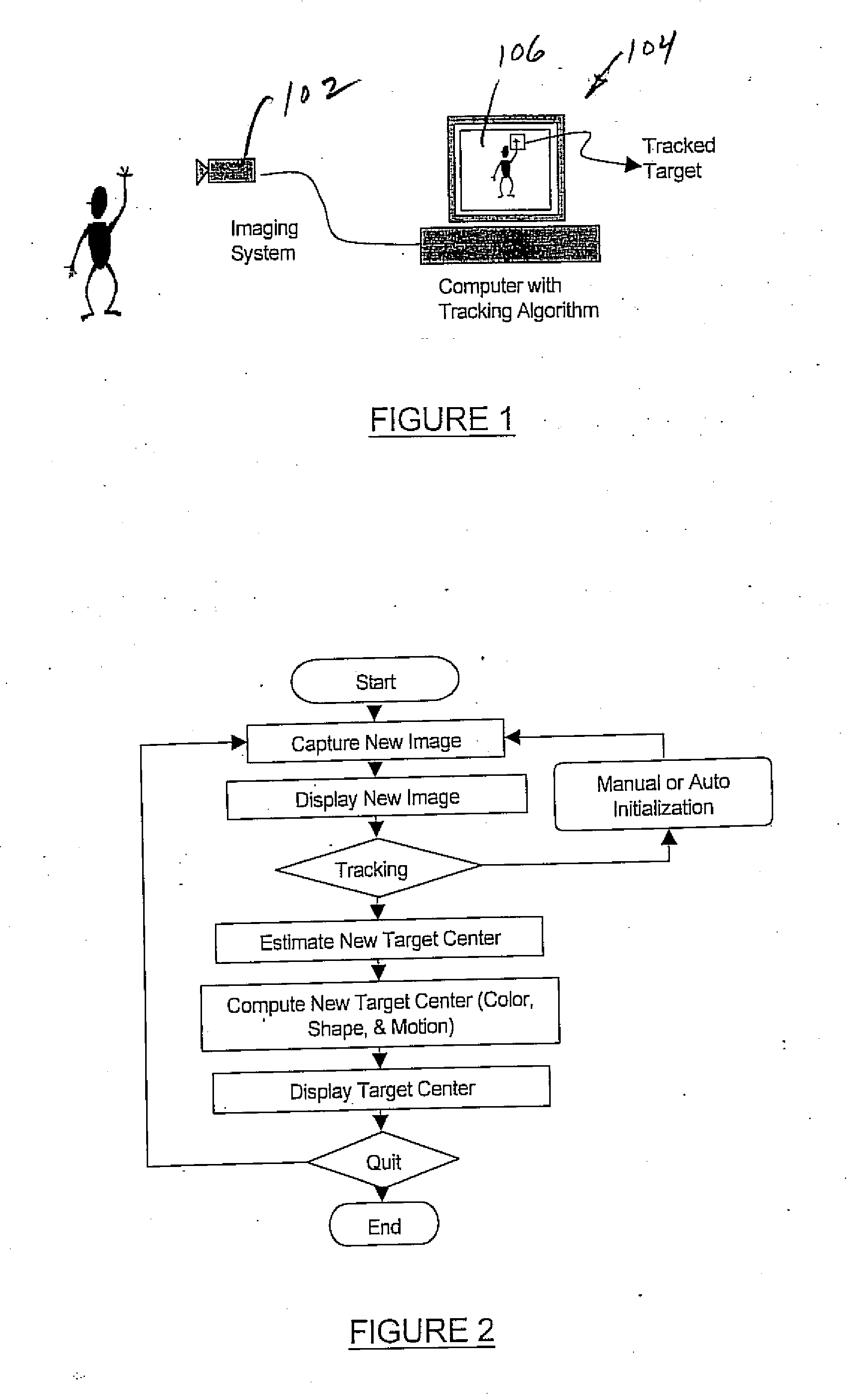
[0021] The flow chart of the tracking algorithm is shown in FIG. 2. The program captures live images from the camera and displays them on the screen. It then allows the user to select the target manually using the mouse or automatically by moving the target to a predetermined position in the scene. At the point of initializatio...


PUM


Abstract

A real-time computer vision system tracks the head of a computer user to implement real-time control of games or other applications. The imaging hardware includes a color camera, frame grabber, and processor. The software consists of the low-level image grabbing software and a tracking algorithm. The system tracks objects based on the color, motion and / or shape of the object in the image. A color matching function is used to compute three measures of the target's probable location based on the target color, shape and motion. The method then computes the most probable location of the target using a weighting technique. Once the system is running, a graphical user interface displays the live image from the color camera on the computer screen. The operator can then use the mouse to select a target for tracking. The system will then keep track of the moving target in the scene in real-time.

Description

REFERENCE TO PRIOR APPLICATIONS [0001] This application claims priority of U.S. provisional application Ser. No. 60 / 214,991, filed Jun. 29, 2000, and is a continuation-in-part of U.S. patent application Ser. No. 09 / 798,594, filed Mar. 2, 2001, which is a continuation-in-part of U.S. patent application Ser. No. 09 / 371,460, filed Aug. 10, 1999, the entire contents of each application being incorporated herein by reference.FIELD OF THE INVENTION [0002] This invention relates generally to computer vision systems and, in particular, to a real-time head tracking system and method for use in conjunction with computer games and other control applications. BACKGROUND OF THE INVENTION [0003] Current imaging systems can convert live scenes into a sequence of digital images which can be processed to track any object in the scene from frame to frame. The techniques used for tracking are numerous. Most of the currently available systems use some characteristic of the subset of the image containin...

Claims


Application Information

Patent Timeline
Patent Type & Authority Applications(United States)
IPC IPC(8): A63F9/24G06K9/00G06T7/20
CPCA63F13/10A63F2300/1012A63F2300/1087A63F2300/1093G06T2207/30201G06K9/00335G06T7/20G06T7/2046G06T2207/10016A63F2300/69G06T7/73G06T7/251G06T7/90A63F13/42G06V40/20G06F18/22A63F13/213G06F3/012G06T11/20G06T2207/30196
Inventor PAUL, GEORGE V.BEACH, GLENN J.COHEN, CHARLES J.JACOBUS, CHARLES J.
Owner JOLLY SEVEN SERIES 70 OF ALLIED SECURITY TRUST I
Why Eureka
Try Eureka