
Method and apparatus for elemental analysis of a fluid downhole

Active Publication Date: 2007-03-29
BAKER HUGHES INC
View PDF15 Cites 74 Cited by
  • Summary
  • Abstract
  • Description
  • Claims
  • Application Information

AI Technical Summary

Benefits of technology

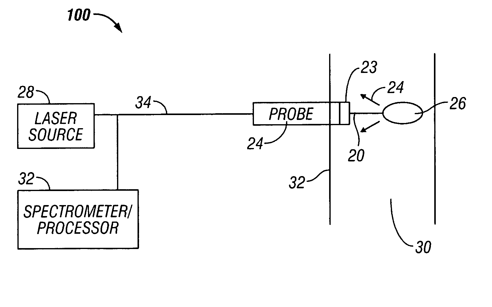
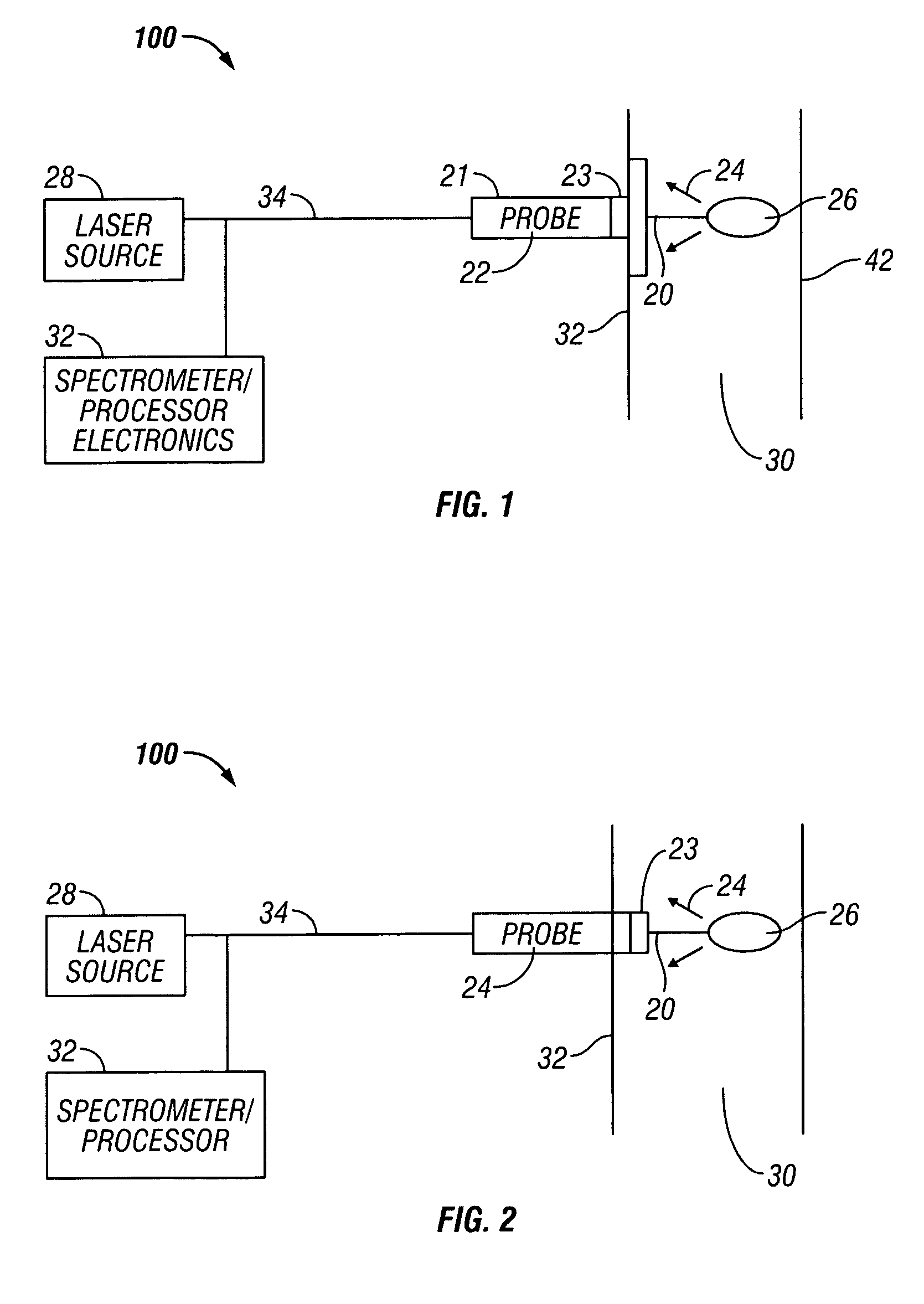
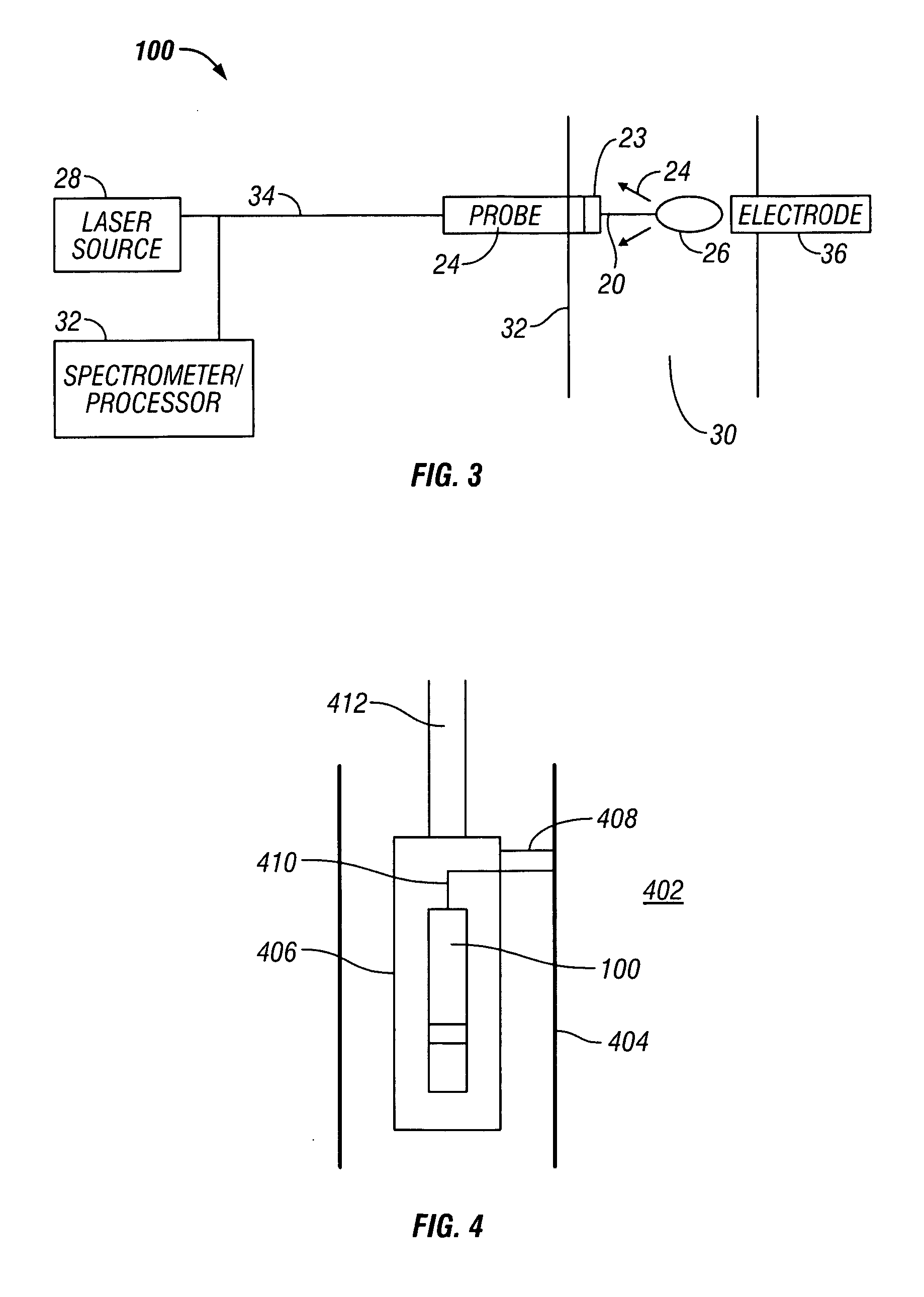
[0006] The present invention provides a method and apparatus for performing elemental analysis of a formation fluid downhole. The present invention provides elemental analysis of a formation fluid downhole using breakdown spectroscopy. Plasma is induced in a fluid under test downhole. Emissions from the plasma are analyzed to determine the composition of the fluid under test. Emissions include but are not limited to light in the ultraviolet, visible, and near infrared regions of the spectrum. A spectrometer is provided for elemental and compositional analysis of a fluid downhole. Compositional analysis yields information about the fluid and the formation from which the fluid originated. In one aspect of the invention, a method and apparatus for performing laser induced breakdown on a formation fluid sample is provided. In another aspect of the invention a method and apparatus are provide for performing spark induced breakdown spectroscopy. It is well known how to apply breakdown spectroscopy in air in the laboratory at room pressure. However, applying this technology downhole presents several challenges. First of all, downhole fluids are typically under tremendous pressures of 10-20 kpsi. Therefore, to apply such a technique downhole, sufficient energy must be applied over a small enough volume within a short enough period of time (for example by using a strong enough laser or a spark), so as to raise the temperature high enough (about 10,000 C) that the pressure within the plasma exceeds the pressure within the fluid. In this way, it becomes possible for a small bubble of plasma to form within the high pressure fluid. Secondly, it must be possible to detect the light coming from this bubble of plasma even though this bubble is immersed within a dark fluid (such as crude oil) that strongly absorbs the light which it emits.

Problems solved by technology

However, applying this technology downhole presents several challenges.

Method used


Image

  • Method and apparatus for elemental analysis of a fluid downhole
  • Method and apparatus for elemental analysis of a fluid downhole
  • Method and apparatus for elemental analysis of a fluid downhole

Examples


Embodiment Construction

[0015] The present invention is susceptible to embodiments of different forms. There are shown in the drawings, and herein will be described in detail, specific embodiments of the present invention. This exemplary disclosure is provided with the understanding that it is to be considered an exemplification of the principles of the invention, and is not intended to limit the invention to that illustrated and described herein. In particular, various embodiments of the present invention provide a number of different constructions and methods of operation, and modifications thereof can be made by one skilled in the art without departing from the spirit and teachings of the invention. It is to be fully recognized that the different teachings of the embodiments discussed below may be employed separately or in any suitable combination to produce desired results.

[0016] The present invention provides a method and apparatus for generating a plasma by using a spark or by applying a laser beam ...


PUM


Abstract

The present invention provides a method and apparatus for performing elemental analysis of a formation fluid downhole. The present invention provides elemental analysis of a formation fluid downhole using breakdown spectroscopy. In one aspect of the invention, a method and apparatus are provided for performing laser induced breakdown on a formation fluid sample is provided. In another aspect of the invention a method and apparatus are provided for performing spark induced breakdown spectroscopy. Plasma is induced in a fluid under test downhole. Emissions from the plasma are analyzed to determine the elemental composition of the fluid under test. Emissions include but are not limited to light in the ultraviolet, visible, and near infrared regions of the spectrum. A spectrometer is provided for elemental analysis of a fluid downhole. Elemental analysis yields information about the fluid and the formation from which the fluid originated.

Description

BACKGROUND OF THE INVENTION [0001] 1. Field of the Invention [0002] The present invention relates to compositional analysis of a fluid sample downhole. More particularly, the present invention relates to the elemental analysis of samples downhole such that they may be analyzed for their constituent components via laser induced breakdown spectroscopy (LIBS), spark-induced breakdown spectroscopy (SIBS) or some similar technique of plasma generation and optical emission analysis. [0003] 2. Summary of Related Art [0004] There are many situations where it is necessary or desirable to obtain substantially instantaneous and / or immediate major and trace constituent analysis of a sample material. Sample materials may include geological samples, soil samples, powder metallurgy, ceramics, food, pharmaceuticals, and many other materials. There are many reasons why it would be desirable to test these materials for their composition of components. Hydrocarbon production is costly and knowing that...

Claims


Application Information

Patent Timeline
IPC IPC(8): E21B47/08
CPCE21B47/102G01J3/443G01N21/6402G01N21/67G01N21/69G01N2021/855G01N21/8507G01N33/2823G01N33/2835G01N2021/8528G01N21/718E21B47/113E21B49/087
Inventor DIFOGGIO, ROCCO
Owner BAKER HUGHES INC
Learn More