Bicycle display device

a display device and bicycle technology, applied in the direction of steering devices, cycle equipments, lighting and heating apparatuses, etc., can solve the problems of chain chatter and shifting that cannot be smoothly accomplished, fine adjustment operation requires considerable time, and the concern of misoperation of shifting gears in fine adjustment mod

Active Publication Date: 2007-03-29
SHIMANO INC
View PDF5 Cites 30 Cited by
  • Summary
  • Abstract
  • Description
  • Claims
  • Application Information

AI Technical Summary

Benefits of technology

[0011] One object of the present invention is to provide a bicycle display device that allows the amount of adjustment to be accurately known when performing the work of fine adjustment of the transmission position.

Problems solved by technology

When the positional relationship between the sprocket and chain guide moving in the axial direction is misaligned in such transmission devices, and particularly in externally mounted transmission devices, the chain chatters and shifting can not be accomplished smoothly.
When the amount of adjustment of the transmission gear position can not be correctly perceived when making this fine adjustment, the amount of completed adjustment, or the amount of possible further adjustment after this adjustment can not be known, such that the fine adjustment operation requires considerable time.
Particularly when performing this fine adjustment while riding, the fine adjustment operation may cause delay since it is difficult to directly verify the chain guide position by visual inspection.
Furthermore, when the operation part for entering the fine adjustment mode to perform the fine adjustment of the chain guide is placed near the hand that performs the gear shifting operation, such as on the handlebar or the like, there is concern of mistakenly entering the fine adjustment mode by misoperation when shifting gears.
When the fine adjustment mode is entered while operating the bicycle, the rider can not perform the gear shifting operation, and there is concern of devastating time loss, particularly when such misoperation occurs during a race.

Method used


Image

  • Bicycle display device
  • Bicycle display device
  • Bicycle display device

Examples


Embodiment Construction

[0050] Selected embodiments of the present invention will now be explained with reference to the drawings. It will be apparent to those skilled in the art from this disclosure that the following descriptions of the embodiments of the present invention are provided for illustration only and not for the purpose of limiting the invention as defined by the appended claims and their equivalents.

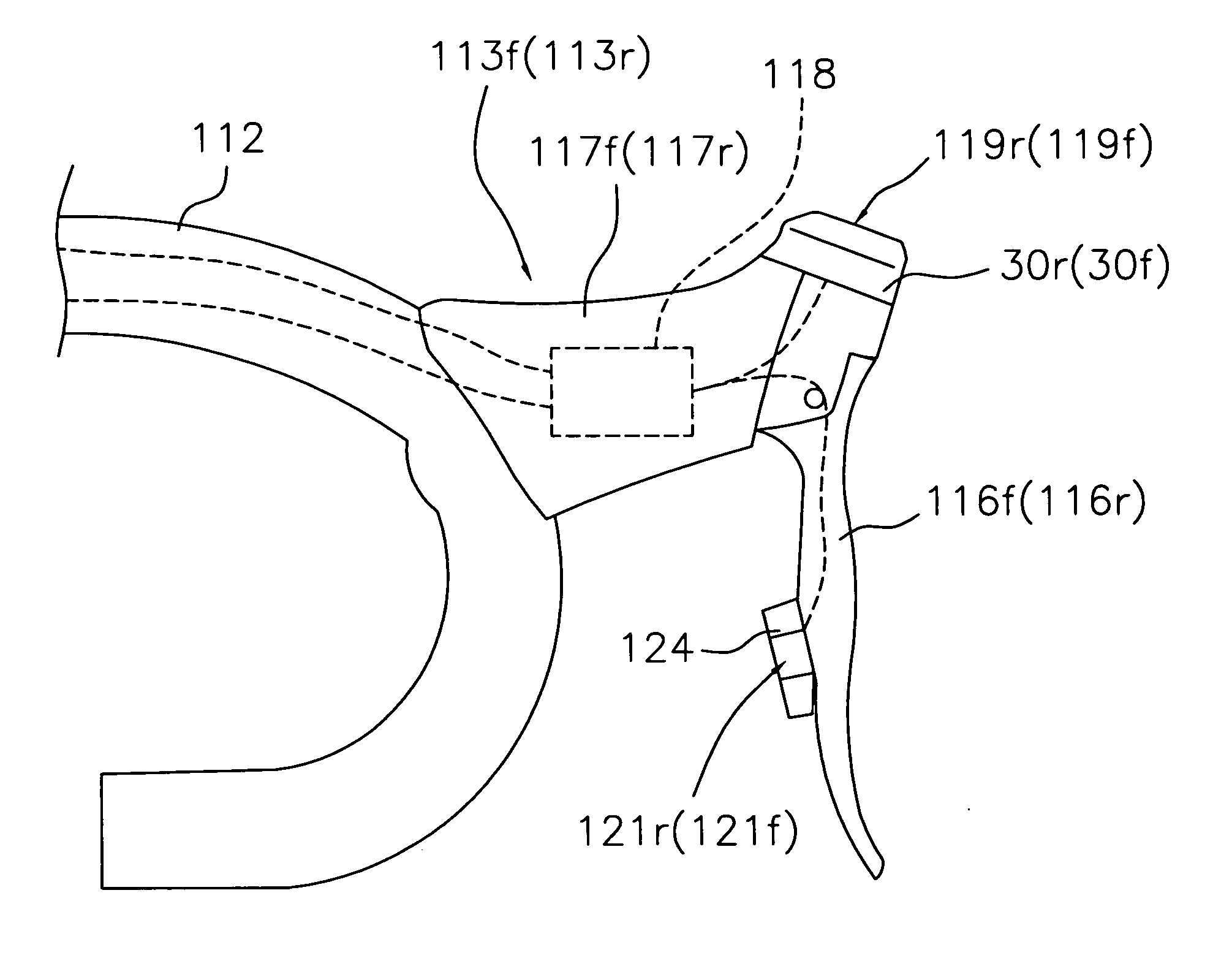
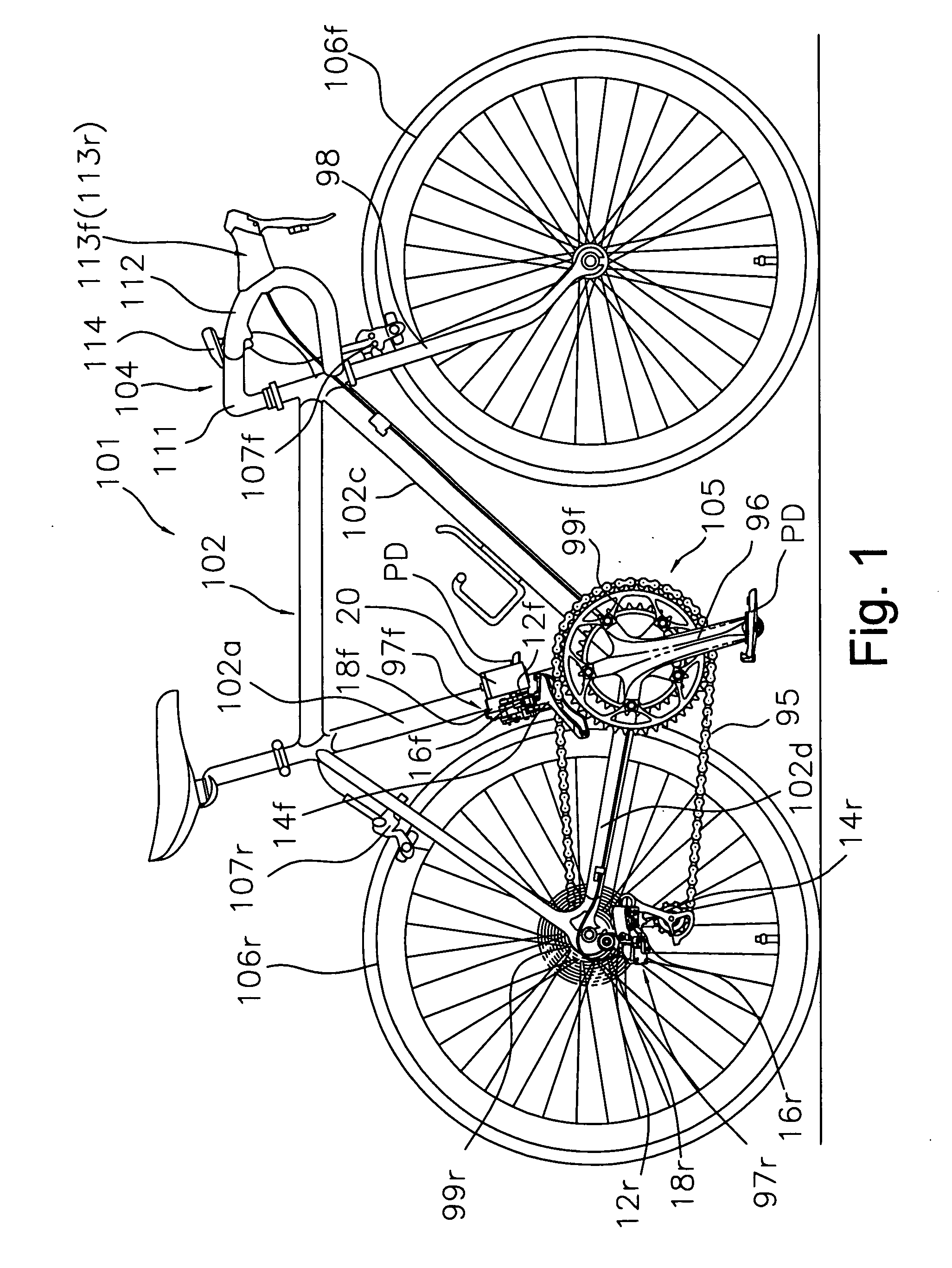
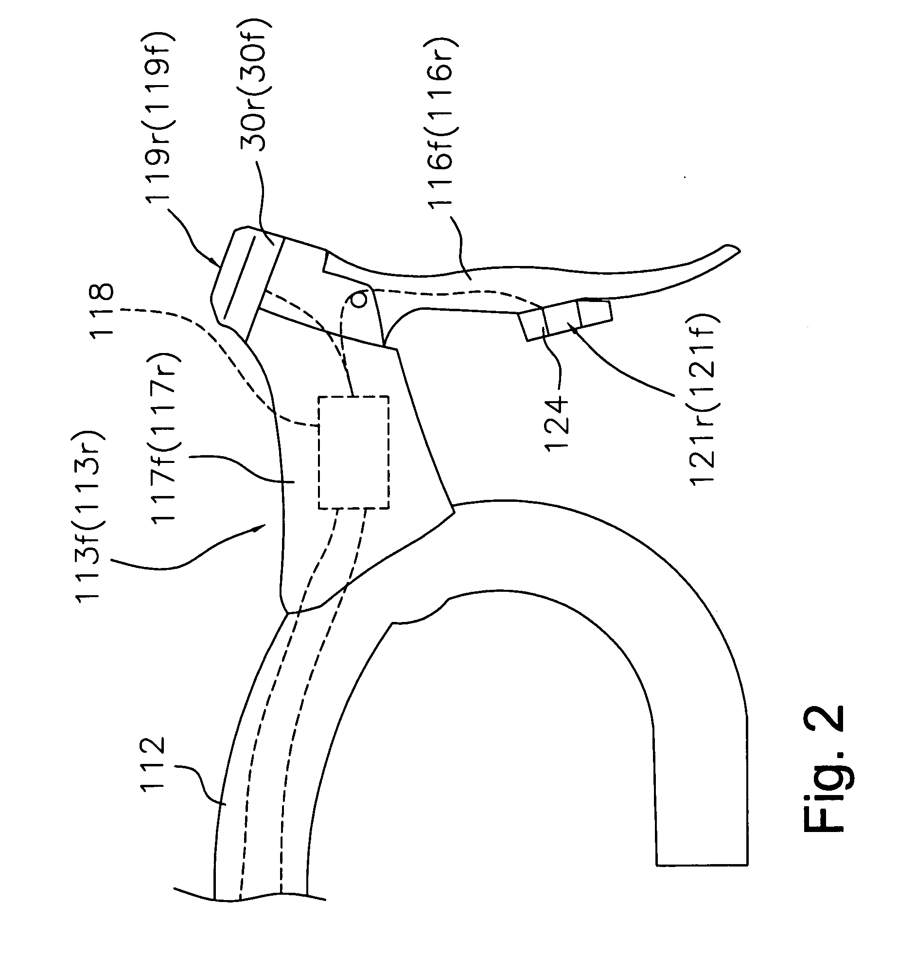
[0051] Referring initially to FIG. 1, a bicycle 101 is illustrated in accordance with a first embodiment of the present invention. As seen in FIG. 1, the bicycle 101 is a “road racer” (racing style road bike) that basically comprises a diamond shaped frame 102, a handlebar unit 104, a drive unit 105, a pair of front and rear wheels 106f and 106r, a pair of front and rear brake devices 107f and 107r and a variable speed gearshift device 110. The diamond shaped frame 102 has a front fork 98 to which the handlebar unit 104 is fastened. The drive unit 105 basically includes a chain 95, a crank 96 wit...


PUM


Abstract

A bicycle display device is configured to accurately verify an amount of adjustment occurring when performing a fine adjustment of a transmission position of a transmission device. The bicycle display device is mounted on a bicycle, and includes a mounting part and a display element. The mounting part is attachable to a brake bracket of the bicycle. The display element is supported by the mounting part, and is configured and arranged to display a fine adjustment display screen for indicating the amount of adjustment when adjusting the transmission position of a transmission device such as a rear derailleur.

Description

CROSS-REFERENCE TO RELATED APPLICATIONS [0001] This application claims priority under 35 U.S.C. § 119 to Japanese Patent Application No. 2005-242695, filed Aug. 24, 2005 and Japanese Patent Application No. 2006-017463, filed Jan. 26, 2006. The entire disclosures of Japanese Patent Application Nos. 2005-242695 and 2006-017463 are hereby incorporated herein by reference. BACKGROUND OF THE INVENTION [0002] 1. Field of the Invention [0003] This invention generally relates to a bicycle display device configured to be mounted on a bicycle. More specifically, the present invention relates a bicycle display device that indicates an amount of adjustment when adjusting a transmission position of a transmission device such as a rear derailleur. [0004] 2. Background Information [0005] Bicycling is becoming an increasingly more popular form of recreation as well as a means of transportation. Moreover, bicycling has become a very popular competitive sport for both amateurs and professionals. Whet...

Claims


Application Information

Patent Timeline
Patent Type & Authority Applications(United States)
IPC IPC(8): B62K21/12B62J99/00
CPCB62J99/00B62J2099/0026Y10T74/20822B62M25/08B62M2025/003B62M25/04B62J50/22
Inventor FUJII, KAZUHIROFUKUDA, MASAHIKOTAKAMOTO, RYUICHIRO
Owner SHIMANO INC
Why Eureka
Try Eureka