Measuring wind vectors remotely using airborne radar

a technology of airborne radar and wind velocity, which is applied in the field of meteorological radar, can solve the problem that radars are only able to resolve six discrete problems, and achieve the effect of improving the accuracy of wind velocity measuremen

Inactive Publication Date: 2007-03-29
THE BOEING CO
View PDF25 Cites 43 Cited by
  • Summary
  • Abstract
  • Description
  • Claims
  • Application Information

AI Technical Summary

Benefits of technology

[0008] In still another aspect of the present invention, the airborne weather radars provided by the present invention are configured and adapted to sweep below (or above) the flight path of the aircraft on which they reside. More particularly, the scan patterns provided by the present invention can include sweeps wherein the surface of the Earth is scanned particularly when the airborne weather radar (or rather, the aircraft on which it resides) is over water. The returns from the water can thus be analyzed to characterize pre-selected surface attributes such as wave amplitude, wavelength, and direction of travel. Furthermore, this information can be correlated with low-altitude wind velocities over the body of water. This advantage of the present invention allows these low-altitude winds to be measured remotely despite the possibility that the weak radar returns generated by the atmospheric aerosols can be overwhelmed by ground clutter. Additionally, these surface returns may also be used for other types of remote sensing that are unrelated to winds velocity measurement. The present invention also provides a computer that combines navigation data from the aircraft with measurements of wind velocity made with airborne weather radars. The computer can be on the aircraft that carries the weather radar or on the ground, depending in part on the relative cost of air-to-ground communication verse onboard computational power.
[0009] In another preferred embodiment, the invention includes networks, systems, and methods to combine wind velocity data from multiple airborne weather radars. Each of the wind velocity. measurements may be made at different locations or some of the measurements may be made at the same location. In the case in which the measurements are made at the same location, the multiple measurements can be mathematically combined (for example by the root sum squares method) to improve the accuracy of the wind velocity measurement. One source of improvement in the measurement arises from the direction from which each of the multiple measurements is made. This is significant in that each Doppler velocity measurement detects one component of the velocity along the direction of the radar return. Thus, with multiple measurements made from different directions multiple velocity components are measured. These components can then be down-linked to a facility and analyzed to determine the overall wind speed and direction (i.e., the velocity). The analysis includes combining navigation data from the aircraft involved and the measured wind velocities. Accordingly, the present invention is relatively insensitive to sensing, or viewing, geometry. In another preferred embodiment, the weather radar is configured and adapted to also scan to either side of the aircraft's flight path.
[0010] In yet another preferred embodiment, the present invention provides a computer network for building weather models from the meteorological property profiles. The network of the current embodiment includes remote profiling instruments (e.g., “vertical profilers”) mounted on commercial aircraft, unmanned aerial vehicles, or other mobile platforms which are networked together via a communications network or system. Each of the vehicles therefore represents a sensing node of the network. Since the sensing nodes are mobile, the present invention allows gathering profiles over a larger region than was heretofore possible. A modeling node with a processor communicates with the sensing nodes to receive the gathered profiles and use them as inputs to a three dimensional weather model. The processor can also use the model to forecast the weather in the region where the profiles were gathered or even over adjacent areas.
[0011] Further features and advantages of the present invention, as well as the structure and operation of various embodiments of the present invention, are described in detail below with reference to the accompanying drawings.

Problems solved by technology

Moreover, these previously available radars are only able to resolve six discrete levels of precipitation.

Method used


Image

  • Measuring wind vectors remotely using airborne radar
  • Measuring wind vectors remotely using airborne radar
  • Measuring wind vectors remotely using airborne radar

Examples


Embodiment Construction

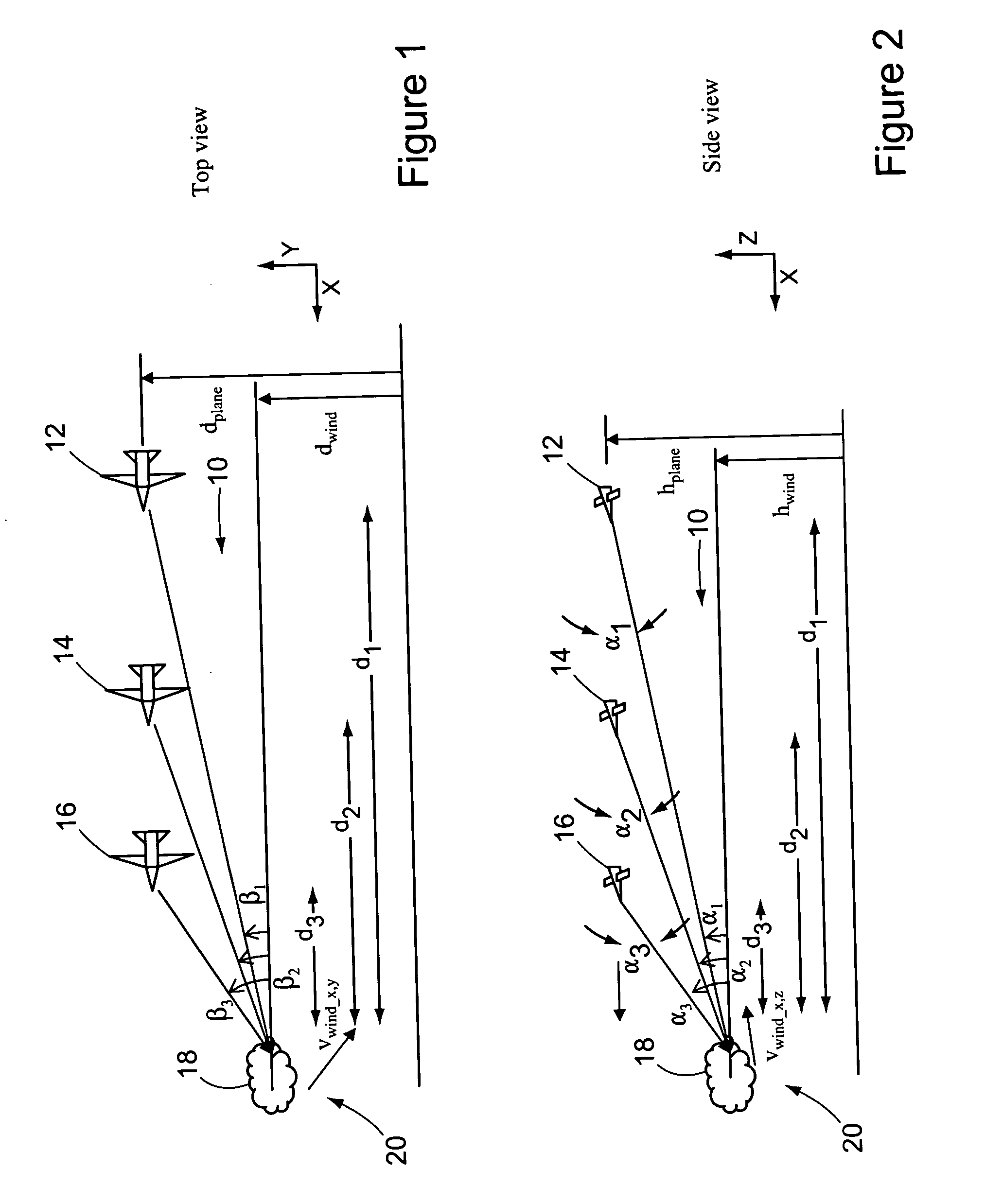
[0017] Referring to the accompanying drawings in which like reference numbers indicate like elements, FIG. 1 illustrates a wind vector measuring system constructed in accordance with the principles of the present invention.

[0018] The exemplary system 10 shown in FIG. 1 includes several aircraft 12, 14, and 16 equipped with airborne meteorological radar units (hereinafter “weather radars”) that typically detect precipitation 18 (shown schematically as a cloud) in the projected flight path of the aircraft 12, 14, and 16. Of course, the several aircraft 12, 14, and 16 could instead be one aircraft shown at different times as it travels along its flight path. The weather radars aboard the aircraft 12, 14, and 16 have been modified to detect the wind velocity vwind not only along the projected flight path(s) but also in areas 20 offset from the flight path. For example, the area 20 where the wind velocity vwind will be measured is shown in FIG. 1 as being offset from the projected fligh...


PUM


Abstract

Airborne meteorological radars and related networks and models. In one embodiment a network for creating a meteorological model includes a mobile sensing node and a modeling node. The sensing node includes a meteorological RADAR that senses the wind velocity. Data from the meteorological RADAR regarding the wind velocity is received by a processor of the modeling node which determines a model of the wind from the wind velocity. The modeling node combines data from a second sampling node with the data from the first sampling node to create a resultant wind velocity vector. Preferably, the modeling node and the sampling node(s) communicate over an airborne WAN. Another embodiment provides a method of measuring the wind velocity. The method includes steering an RADAR signal out of the plane of travel of the mobile platform. The wind velocity is measured using a return of the RADAR signal.

Description

RELATED APPLICATIONS [0001] This application is a continuation in part of U.S. patent application Ser. No. 11 / 235,371, entitled Airborne Weather Profiler Network, filed by Tillotson on Sep. 26, 2005, which is incorporated herein as if set forth in full.FIELD OF THE INVENTION [0002] This invention relates generally to meteorological radars and, more particularly, to airborne meteorological radars adapted to measure wind related Doppler effects with a high degree of resolution. BACKGROUND OF THE INVENTION [0003] Current meteorological models are limited in their capabilities by the quality and quantity of available weather data. In particular, the sensors that gather weather data are few and far between in remote areas such as deserts, the polar regions, and oceans. The Eastern Pacific Ocean is one such example and has only a few weather buoys scattered along thousands of miles of United States coast. Since weather moves in from the Pacific in the western United States, the lack of da...

Claims


Application Information

Patent Timeline
Patent Type & Authority Applications(United States)
IPC IPC(8): G01S13/95
CPCG01S7/003G01S17/95G01S13/953Y02A90/10
Inventor PEARLMAN, JAY S.TILLOTSON, BRIAN J.
Owner THE BOEING CO
Why Eureka
Try Eureka