Image forming apparatus

a technology of image forming and forming drum, which is applied in the direction of optics, printing, instruments, etc., can solve the problems of difficult to determine with a high precision the positional relationship of the overlapping portions of the image bar or the led head arranged in a zigzag arrangement, and the device is very expensive, so as to achieve the effect of increasing the width of the photoconductive drum or

Inactive Publication Date: 2007-03-29
FUJIFILM BUSINESS INNOVATION CORP
View PDF6 Cites 17 Cited by
  • Summary
  • Abstract
  • Description
  • Claims
  • Application Information

AI Technical Summary

Benefits of technology

[0009] The invention is made in consideration of the above-mentioned problems of the related arts, and an advantage of the invention is to provide an image forming apparatus that is capable of adjusting overlapping portions of LED heads with a high precision so as not to cause black or white streaks, and at the same time, infinitesimally adjusting the printing magnification so as to reduce the dimensional errors of the images to be formed.
[0010] In order to achieve the above-mentioned advantage, one aspect of the invention provides an image forming apparatus capable of forming wide images. The image forming apparatus includes an exposing unit having a plurality of LED (light-emitting diode) heads arranged alternately in a main scanning direction, in which the resolution of an LED row formed in at least one of the plurality of LED heads is higher than the resolution of image data in a main scanning direction. The image forming apparatus further includes a lighting control unit that controls to turn on or turn off dots in the LED row such that the exposing position of a photoconductive drum is moved in the unit of dots in the high resolution LED row.
[0011] Another aspect of the invention provides an image forming apparatus capable of forming wide images which includes an exposing unit having a plurality of LED (light-emitting diode) heads arranged alternately in a main scanning direction, in which the resolution of an LED row formed in at least one of the plurality of LED heads is higher than the resolution of image data in a main scanning direction. The image forming apparatus further includes a lighting control unit that controls to turn on or turn off dots in the LED row such that the exposing width of a photoconductive drum is increased or decreased in the unit of dots of the high resolution LED row.
[0012] Another aspect of the invention provides an image forming apparatus capable of forming wide images which includes an exposing unit having a plurality of LED (light-emitting diode) heads arranged alternately in a main scanning direction, in which the resolution of an LED row formed in at least one of the plurality of LED heads is higher than the resolution of image data in the main scanning direction. The image forming apparatus further includes a lighting control unit that controls the on / off of dots in the LED row so that the exposing width of a photoconductive drum is increased / decreased in the unit of dots of the high resolution LED row.

Problems solved by technology

An image bar used for wide exposure so as to form wide images, such as A0 size or A1 size, is not general and thus its device is very expensive.
However, the above-mentioned techniques according to the related arts, it is difficult to determine with a high precision the positional relationship of the overlapping portions of the image bars or LED heads arranged in a zigzag pattern, i.e., the dots formed at the end portions in each of the image bars or the LED heads.
Meanwhile, since the meter system has been used as the unit in Japan when the LED heads are manufactured, there are problems that dimensional errors may occur as much as the fractional number generated at the time of unit conversion.
The dimensional errors become conspicuous as the size of the LED heads become larger.
Also, a paper may be shrunk by heating the paper when fixing the toner images on the paper and the shrunk paper may cause the dimensional errors, which is also problematic.

Method used


Image

  • Image forming apparatus
  • Image forming apparatus
  • Image forming apparatus

Examples


Embodiment Construction

[0020] Hereinafter, the best mode for carrying out the present invention (hereinafter, referred to as an embodiment) will be described with reference to drawings.

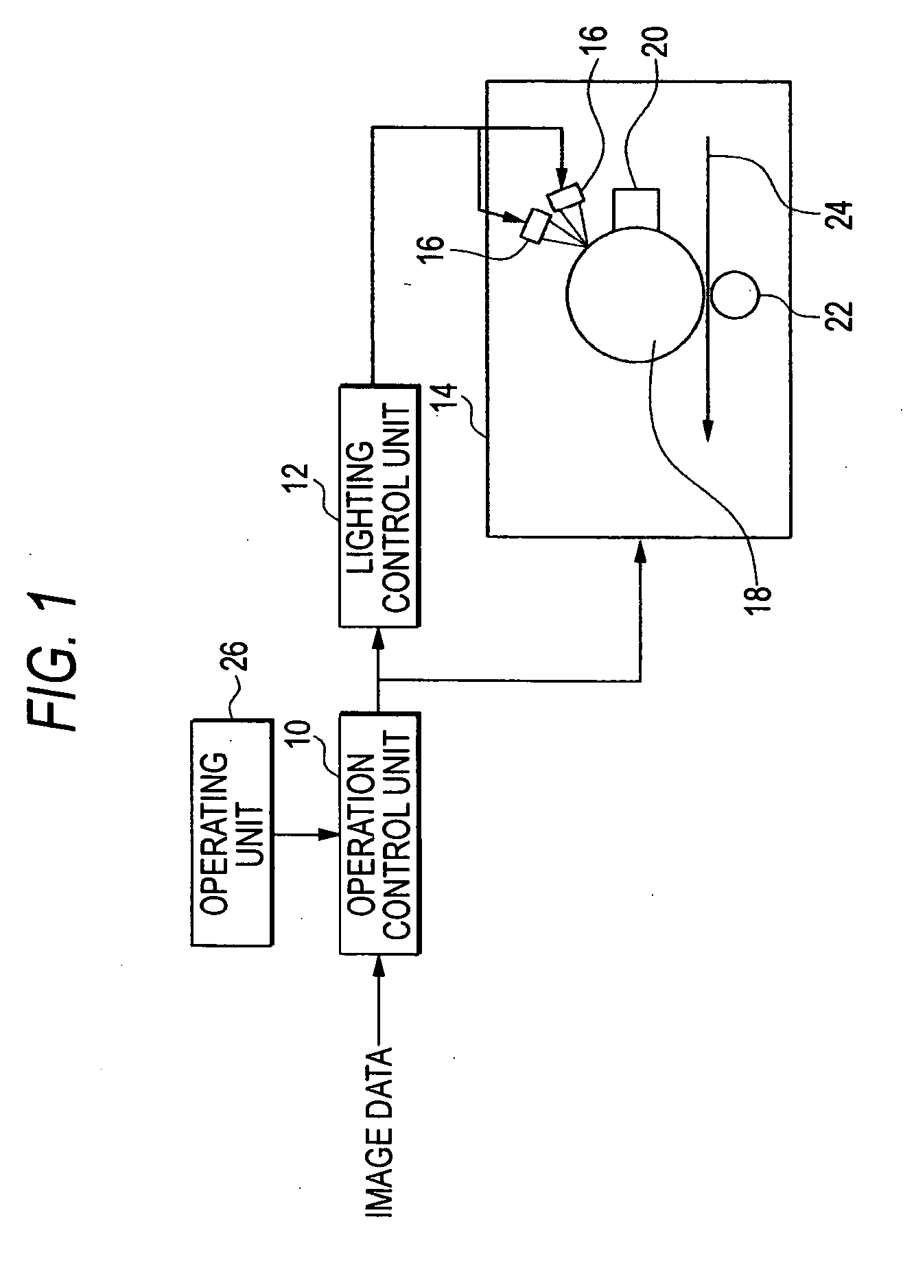
[0021]FIG. 1 is a block diagram showing an image forming apparatus of one embodiment according to the invention. In FIG. 1, the image forming apparatus includes an operation control unit 10, a lighting control unit 12, an image forming unit 14, LED heads 16, and an operating unit 26.

[0022] The operation control unit 10 obtains image data from a scanner or other computers, etc., and instructs the lighting control unit 12, etc., to control the image forming operations of the image forming apparatus according to the obtained image data.

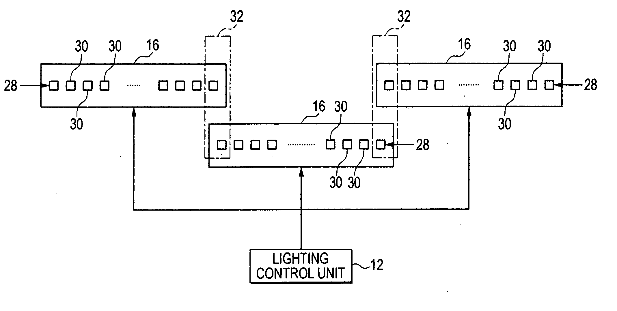
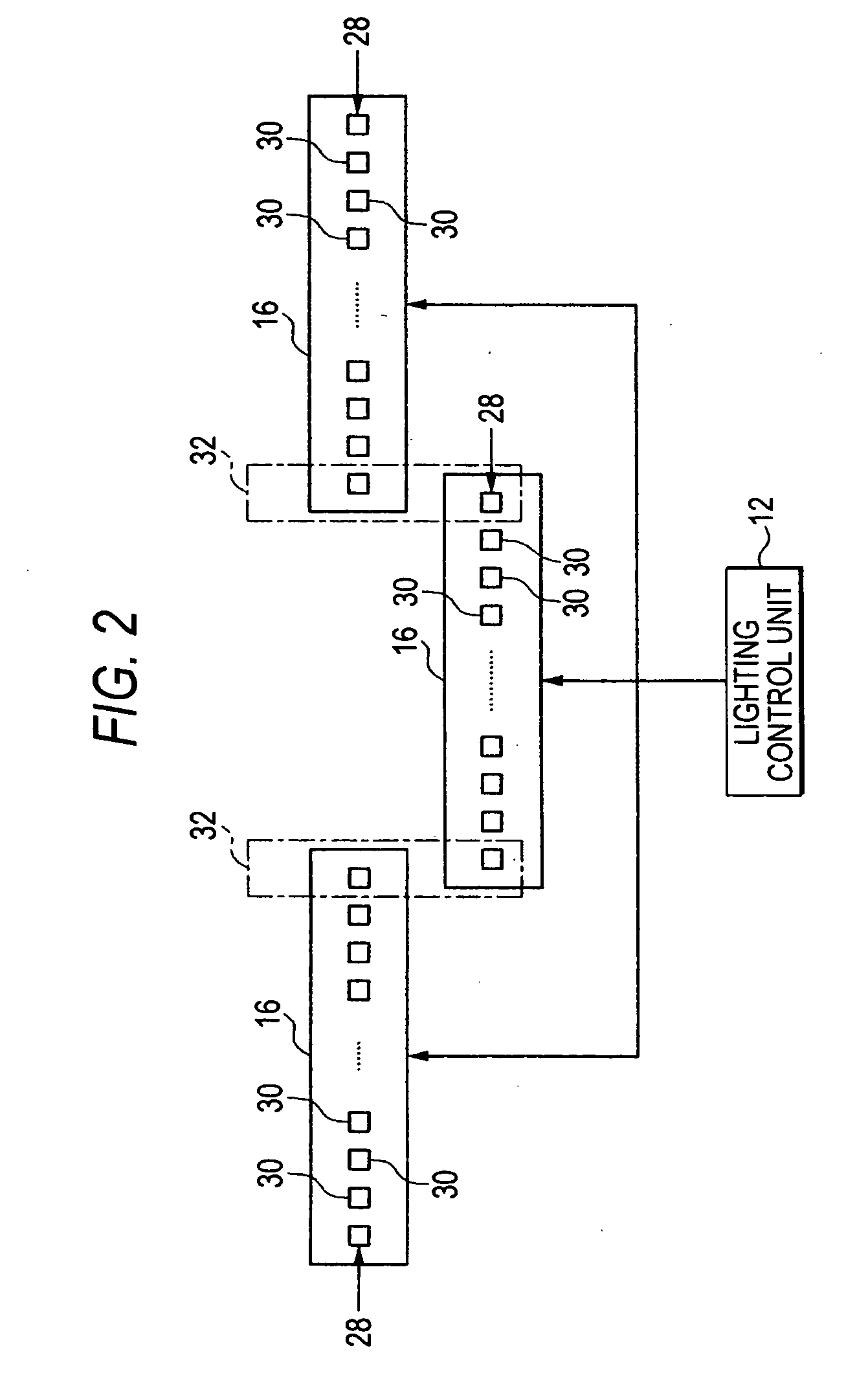
[0023] The lighting control unit 12 controls on / off of each of the light-emitting diodes in an LED row formed in each of the LED heads 16.

[0024] The image forming unit 14 includes a photoconductive drum 18, a developing unit 20, a transfer roll 22, or the like in addition to the LED heads 16...


PUM


Abstract

An image forming apparatus capable of forming wide images, includes: an exposing unit having a plurality of LED (light-emitting diode) heads arranged alternately in a main scanning direction, in which the resolution of an LED row formed in at least one of the plurality of LED heads is higher than the resolution of image data in a main scanning direction; and a lighting control unit that controls to turn on or turn off dots in the LED row such that the exposing position of a photoconductive drum is moved in the unit of dots of the high resolution LED row.

Description

BACKGROUND OF THE INVENTION [0001] 1. Field of the Invention [0002] The present invention relates to improvement on an image forming apparatus that is capable of forming wide images. [0003] 2. Background Art [0004] An image bar used for wide exposure so as to form wide images, such as A0 size or A1 size, is not general and thus its device is very expensive. Consequently, some techniques have been proposed to arrange a plurality of A3 or A4 size image bars, which are generally used, to conduct the wide exposure. [0005] For example, JP-A-6-258727 discloses an apparatus that is capable of conducting an exposure on a photoconductor in a direct line by arranging a plurality of image bars included in a liquid crystal structure. [0006] Also, JP-A-6-255175 discloses an example of a plurality of LED (light-emitting diode) heads arranged in a zigzag pattern. [0007] However, the above-mentioned techniques according to the related arts, it is difficult to determine with a high precision the pos...

Claims


Application Information

Patent Timeline
Patent Type & Authority Applications(United States)
IPC IPC(8): B41J2/385
CPCB41J2/45
Inventor MIKAMI, MASATOMAIE, KUNIHIROTSUTSUMI, KOUJIYANO, SHINGO
Owner FUJIFILM BUSINESS INNOVATION CORP
Why Eureka
Try Eureka