
Electro-Optic Imaging Fourier Transform Spectrometer

a four-dimensional transform, optical imaging technology, applied in the field of optical instruments, can solve the problems of large power consumption, large moving parts, and large size of interferometers, and achieve the effects of reducing the number of moving parts, reducing the accuracy of alignment, and consuming relatively large amounts of power

Inactive Publication Date: 2007-03-29
CALIFORNIA INST OF TECH
View PDF2 Cites 20 Cited by
  • Summary
  • Abstract
  • Description
  • Claims
  • Application Information

AI Technical Summary

Benefits of technology

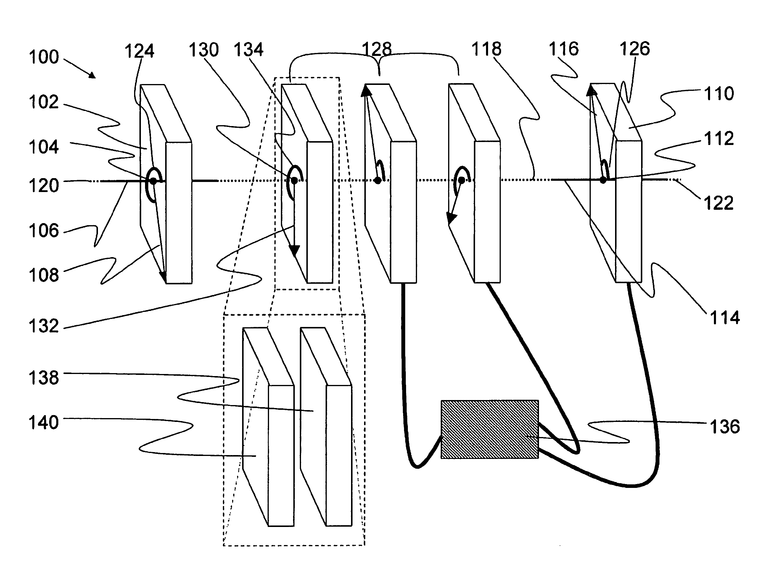
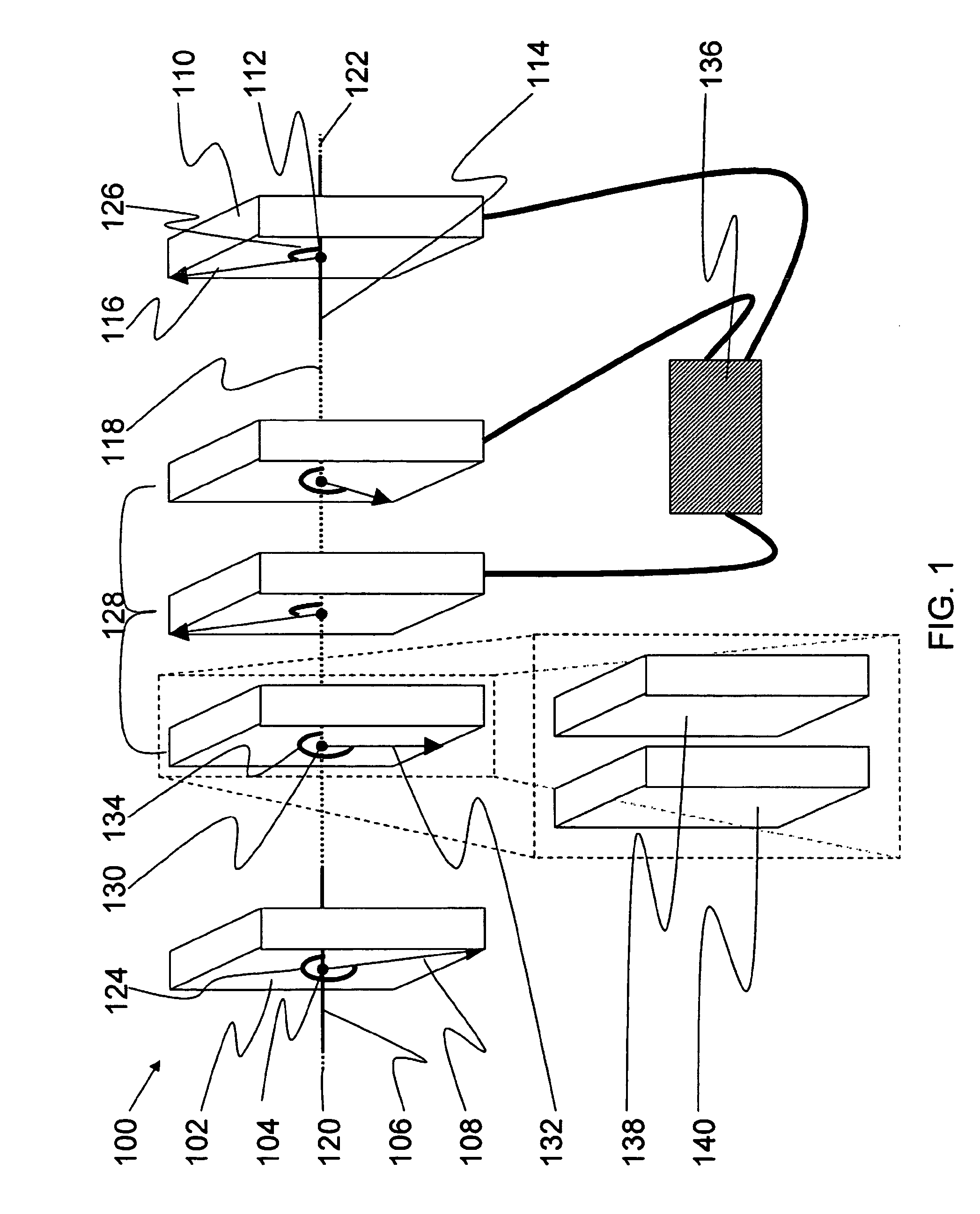
[0011] The spectrometer also comprises a plurality of birefringent phase elements residing between the input polarizer and the output polarizer. The birefringent phase elements include a birefringent phase element center point and a birefringent phase element azimuth vector originating on the birefringent phase element center point. The birefringent phase element azimuth vector point substantially perpendicular to the long axis, thus defining a birefringent phase element orientation between the birefringent phase element azimuth vector and the long axis. At least one orientation is selected from the group consisting of the input polarizer orientation, the output polarizer orientation, and any of the birefringent phase element orientations, allowing the user to substantially reproduce Fourier components of frequency spectra of light passing fully through spectrometer substantially parallel to the long axis.

Problems solved by technology

However, because of the necessity to move large distances, such interferometers tend to be very large, heavy, slow, have many moving parts, require ultra-precise alignment, and consume relatively large amounts of power to operate.

Method used


Image

  • Electro-Optic Imaging Fourier Transform Spectrometer
  • Electro-Optic Imaging Fourier Transform Spectrometer

Examples


Embodiment Construction

[0020] The present invention relates to spectrometer and more particularly to an electro-optic imaging Fourier transform spectrometer for hyperspectral imaging. The following description is presented to enable one of ordinary skill in the art to make and use the invention and to incorporate it in the context of particular applications. Various modifications, as well as a variety of uses in different applications will be readily apparent to those skilled in the art, and the general principles defined herein may be applied to a wide range of embodiments. Thus, the present invention is not intended to be limited to the embodiments presented, but is to be accorded the widest scope consistent with the principles and novel features disclosed herein.

[0021] In the following detailed description, numerous specific details are set forth in order to provide a more thorough understanding of the present invention. However, it will be apparent to one skilled in the art that the present invention...


PUM


Abstract

An Electro-Optic Imaging Fourier Transform Spectrometer (EOIFTS) for Hyperspectral Imaging is described. The EOIFTS includes an input polarizer, an output polarizer, and a plurality of birefringent phase elements. The relative orientations of the polarizers and birefringent phase elements can be changed mechanically or via a controller, using ferroelectric liquid crystals, to substantially measure the spectral Fourier components of light propagating through the EIOFTS. When achromatic switches are used as an integral part of the birefringent phase elements, the EIOFTS becomes suitable for broadband applications, with over 1 micron infrared bandwidth.

Description

PRIORITY CLAIM [0001] The present application is a non-provisional utility patent application, claiming the benefit of priority of U.S. Provisional Patent Application No. 60 / 1715,370, filed Sep. 7, 2005, titled, “ELECTRO-OPTIC IMAGING FOURIER TRANSFORM SPECTROMETER (EOIFTS) FOR HYPERSPECTRAL IMAGING.”GOVERNMENT RIGHTS [0002] The invention described herein was made in the performance of work under a NASA contract, and is subject to the provisions of Public Law 96-517 (35 USC 202) in which the Contractor has elected to retain title.BACKGROUND OF THE INVENTION [0003] (1) Field of Invention [0004] The present invention relates to a Spectrometer and more particularly to an electro-optic imaging Fourier transform spectrometer comprising a single optical path in which the intensity of light that exits the spectrometer after the light traverses an input polarizer, a series of adjustable birefringent phase retarders. and an output polarizer is simply related by the total optical phase delay ...

Claims


Application Information

Patent Timeline
IPC IPC(8): G01B9/02
CPCG01J3/2823G01J3/4532G01J3/4531G01J3/447
Inventor CHAO, TIEN-HSINZNOD, HANYING
Owner CALIFORNIA INST OF TECH
Learn More