Underwater adaptive camera housing

a technology for adaptive cameras and underwater housings, applied in the field of underwater camera housings, can solve the problems of current underwater housings for all cameras, increase prices, and introduce additional complexity and diversity

Inactive Publication Date: 2007-03-29
FANTONE STEPHEN J +2
View PDF6 Cites 265 Cited by
  • Summary
  • Abstract
  • Description
  • Claims
  • Application Information

AI Technical Summary

Benefits of technology

[0013] The present invention relates to an underwater adaptive camera housing for providing a watertight enclosure and common control interface for cameras and the like that have remote electronic control capability. The housing preferably includes two or more housing sections that are moveable between an open and a closed position in which a camera of the type described is mounted within an enclosure sealed from exposure to surrounding water. At least one of the sections has a transparent, preferably truncated hemispherical-shaped, picture taking window that permits light to be received by an enclosed camera. A locking arrangement keeps the housing sections from freely opening when in the closed position. An adjustable inner mount secures cameras in the housing at a position in optical alignment with the transparent picture taking window. A second flat window is provided in the housing above the picture taking window for emitting strobe illumination to a scene. A diffuser is mounted outside of the housing forward of the illumination window to control the pattern of illumination over the scene. A controller is mounted within the enclosure and is programmed to send and receive commands and data to an enclosed camera via a standard communications interface (such as USB), preferably using the Picture Transfer Protocol (PTP) standard. Externally mounted on the housing are human-operable signaling controls (e.g., buttons) that transmit signals to the controller, which subsequently transmits predetermined commands to the camera.

Problems solved by technology

Digital cameras with added displays and menu driven selections for control of camera functions and picture taking settings introduce additional complexity and diversity.
As a consequence, makers of underwater camera housings have been forced to provide designs that match the control requirements of individual camera models.
The fact that each camera requires a unique underwater housing obviously results in higher prices since there is no opportunity to take advantage of economies of scale.
In addition to the problems associated with the need for unique underwater camera housings for every camera, other problems exist with current underwater housings for all cameras.
Often they will leak causing damage to the camera equipment they were expected to protect.
In addition, the use of through holes in the housings creates local areas of high stress concentration, which increase with increasing water depth.
Another problem has to do with the optical properties of underwater housings.
However, the use of flat windows introduces undesirable distortion and narrows the camera's inherent field of view.
Moreover, housings with flat transmission windows often cause artificial light from a camera to reflect into the camera where it becomes an unwanted part of the photograph thus degrading its quality.

Method used


Image

  • Underwater adaptive camera housing
  • Underwater adaptive camera housing
  • Underwater adaptive camera housing

Examples


Embodiment Construction

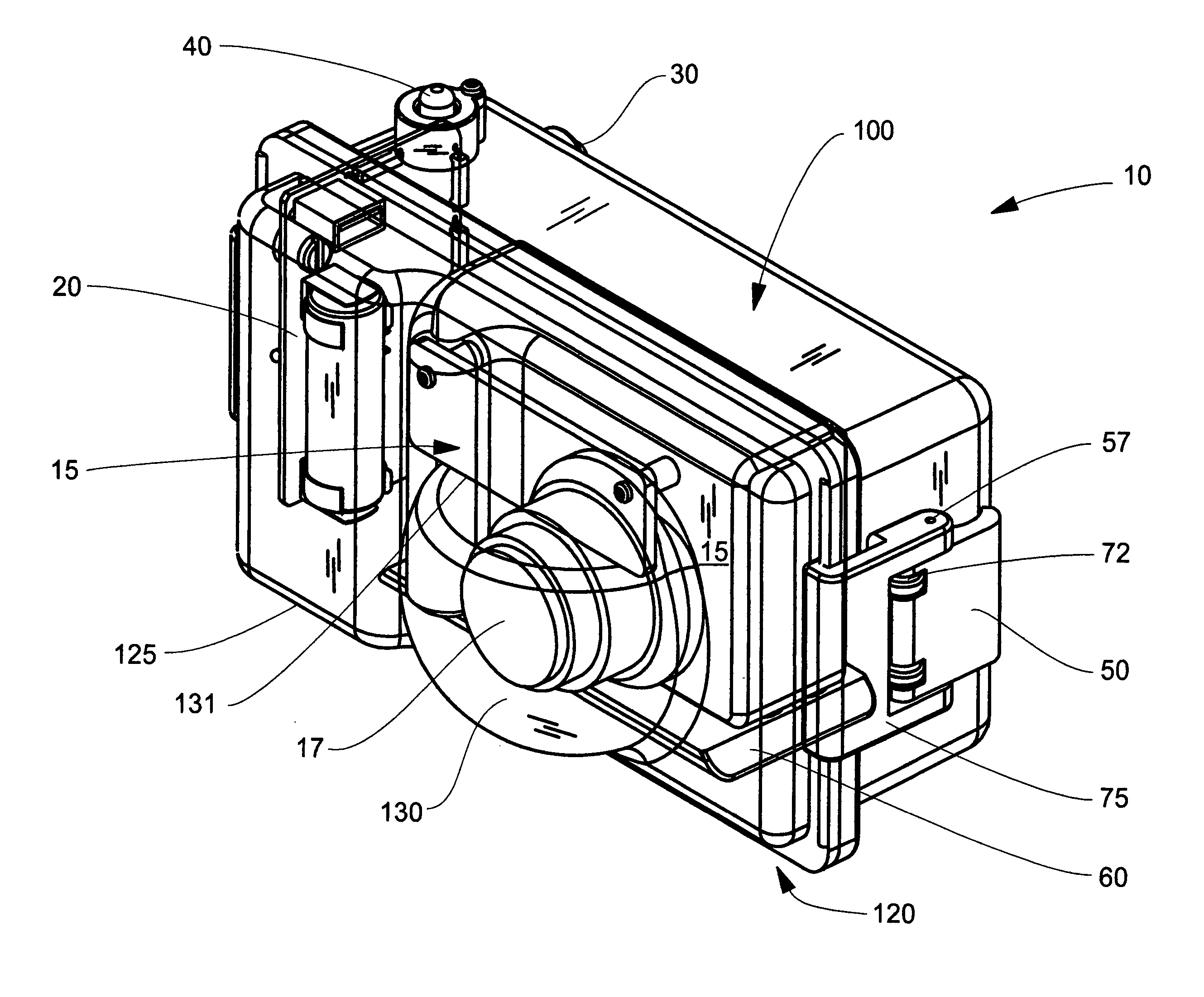
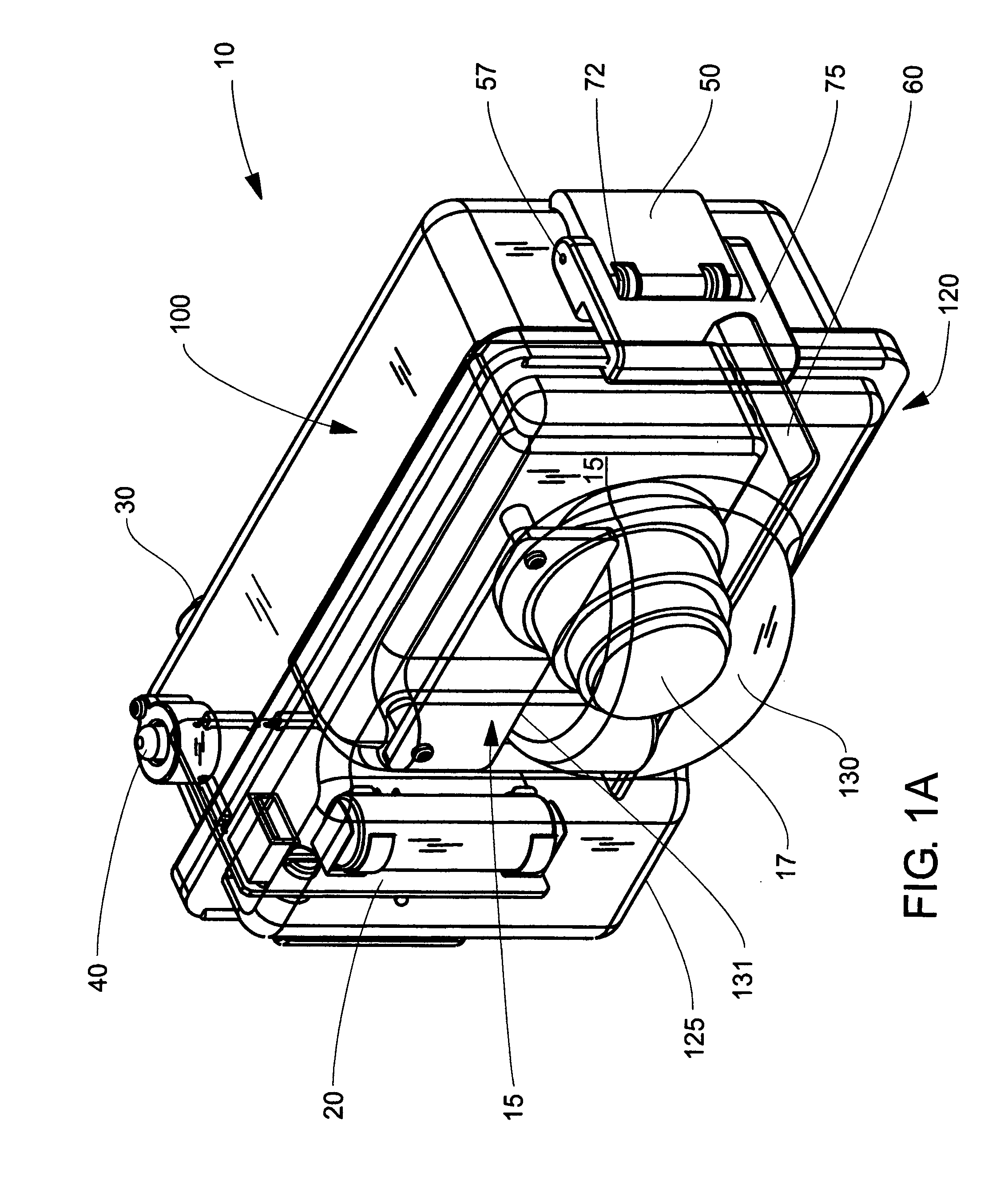
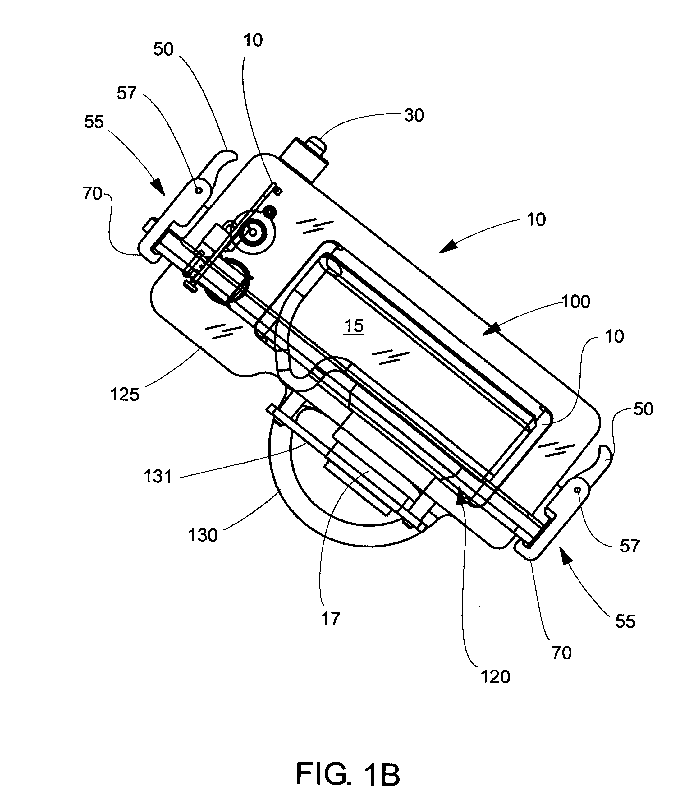
[0030] The present invention relates to an adaptive underwater camera housing and control interface for use with a broad range of camera brands and models. The cameras may BE conventional still and video film cameras, digital still and video cameras, or digital devices provided with photographic capability, such as cell phones or PDAs having integrated digital cameras.

[0031] Reference is now made to FIGS. 1A, 1B, 2 and 3, which show an adaptive underwater camera housing, generally designated at 10, in accordance with the invention along with a digital camera 15 located inside of housing 10. These figures show, respectively, an upper right front perspective view, a diagrammatic top view, an exploded perspective view, and an upper-rear perspective view of the inventive underwater housing 10 including its control interface. FIG. 2 is an exploded perspective view of FIG. 1. As seen in those figures, underwater housing 10 comprises rear and front housing sections, 100 and 120, respectiv...


PUM


Abstract

An adaptive underwater camera housing and control interface for use with a broad range of camera brands and models. The camera housing is preferably formed of front and rear housing sections that are molded of clear transparent plastic and arranged to be moved between an open position for mounting a camera within the housing and a closed position in which the housing provides a watertight enclosure for protecting and communicating with a camera. Residing in the housing are a controller and communications interface by which a camera can be operated from outside the housing. Magnetic signals are preferably passed to the controller by external signal buttons operated by the user. The external signal buttons do not penetrate the interior surfaces of the housing thereby enhancing its water tightness. The housing is provided with a truncated hemispherical lens through which a camera views scenes to be photographed to reduce distortion and not foreshorten viewing angle and a flat window and diffuser for providing controlled artificial illumination to a scene.

Description

CROSS REFERENCE TO RELATED APPLICATIONS [0001] This application claims the benefit of priority from earlier filed U.S. Provisional Patent Application No. 60 / 720,705 filed on Sep. 27, 2005 with the title UNDERWATER ADAPTIVE CAMERA HOUSING and U.S. Provisional Patent Application No. 60 / 830,224 filed on Jul. 12, 2006 with the title UNDERWATER ADAPTIVE CAMERA HOUSING, the contents of both of which are incorporated herein by reference.BACKGROUND OF THE INVENTION [0002] This invention in general relates to housings for conventional cameras (film or digital, but primarily digital) and other digital devices with integral photographic capability to be used for underwater applications and, more particularly, to underwater camera housings having exterior controls that do not extend through the wall of the housing forming the watertight enclosure in which the camera resides. [0003] For a variety of reasons, camera manufacturers do not adhere to any standard layout for the arrangement, function,...

Claims


Application Information

Patent Timeline
Patent Type & Authority Applications(United States)
IPC IPC(8): G03B17/08
CPCG03B17/08
Inventor FANTONE, STEPHEN J.FANTONE, STEPHEN D.PUTHUSSERY, SHAJU M.
Owner FANTONE STEPHEN J
Why Eureka
Try Eureka