Optical receiving apparatus and dispersion compensating method therein

a technology of optical receiving apparatus and optical receiving apparatus, which is applied in the direction of electrical apparatus, distortion/dispersion elimination, fibre transmission, etc., can solve the problems of long-time communication disconnection state, the worst-case disconnection of communication in the network, etc., and achieve excellent signal light receiving

Inactive Publication Date: 2007-03-29
FUJITSU LTD +1
View PDF4 Cites 36 Cited by
  • Summary
  • Abstract
  • Description
  • Claims
  • Application Information

AI Technical Summary

Benefits of technology

[0018] According to the present invention, when a route change (switch) of the received signal light is detected, the dispersion compensation quantity used by the tunable dispersion compensator is adjusted (optimized) according to the optimum dispersion compensation quantity for the received signal light after the route change, which is beforehand stored in the memory. Therefore, it is possible to realize excellent signal light receiving without causing occurrence of a communication disconnection even when a route change occurs.

Problems solved by technology

However, in the case of large-capacity optical transmission at 40 Gbps or the like, if the dispersion is compensated at the receiving end and the dispersion compensation quantity is optimized according to the state of each of the lines (of the working system and the protection system), disconnection of the communication in the network might occur in the worst case.
Even if the technique disclosed in the above patent document 1, which estimates the total dispersion quantity from an electric signal obtained by photo-electrically converting received signal light and determines the identification threshold value and the identification timing of the received data without detecting a line switching, is applied to such event, a time might be required until the dispersion compensation quantity is stabilized at the optimum dispersion compensation quantity after the routing is changed (sweep operation), which causes occurrence of a long-time communication disconnection state.

Method used


Image

  • Optical receiving apparatus and dispersion compensating method therein
  • Optical receiving apparatus and dispersion compensating method therein
  • Optical receiving apparatus and dispersion compensating method therein

Examples


first embodiment

[1] Description of First Embodiment

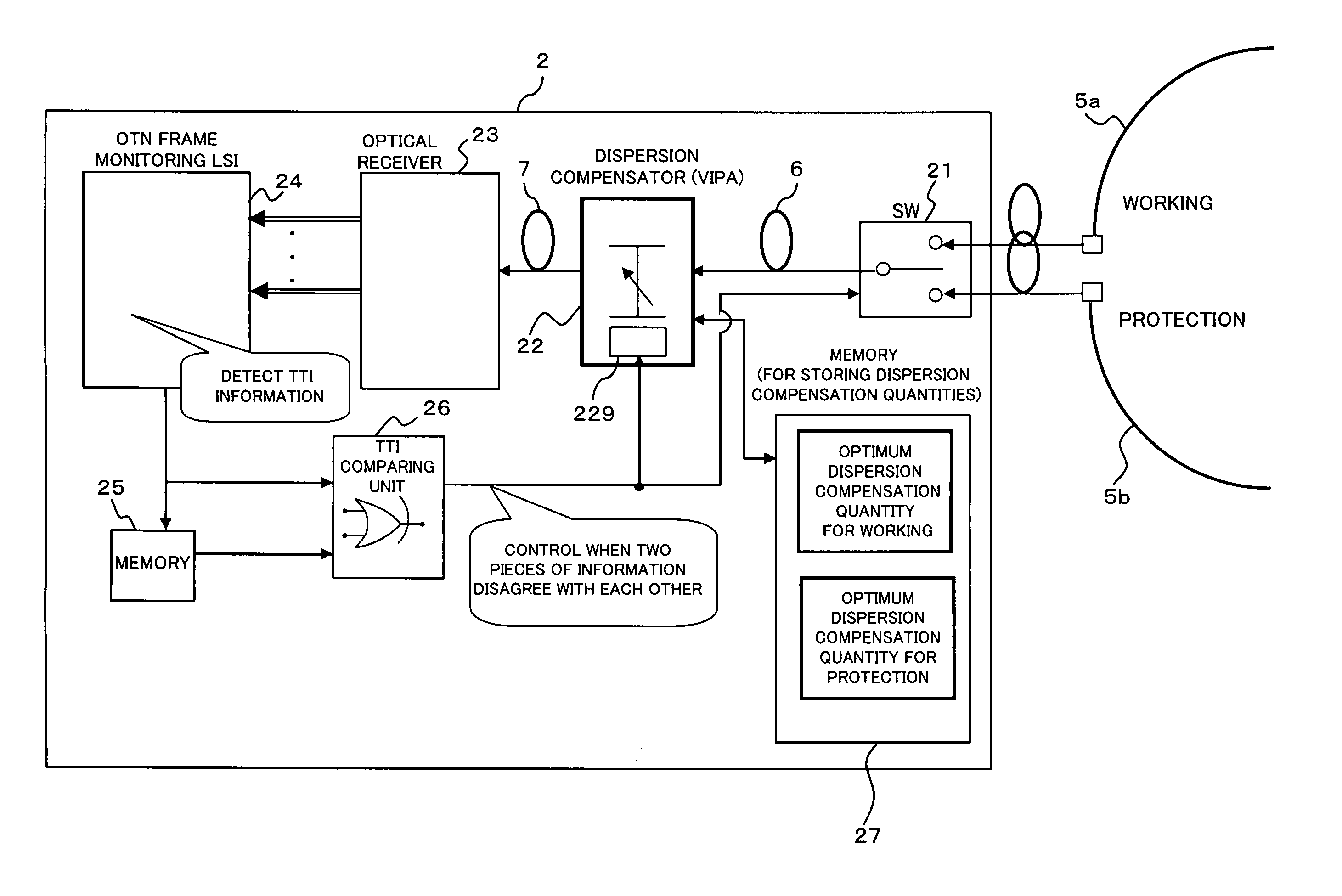
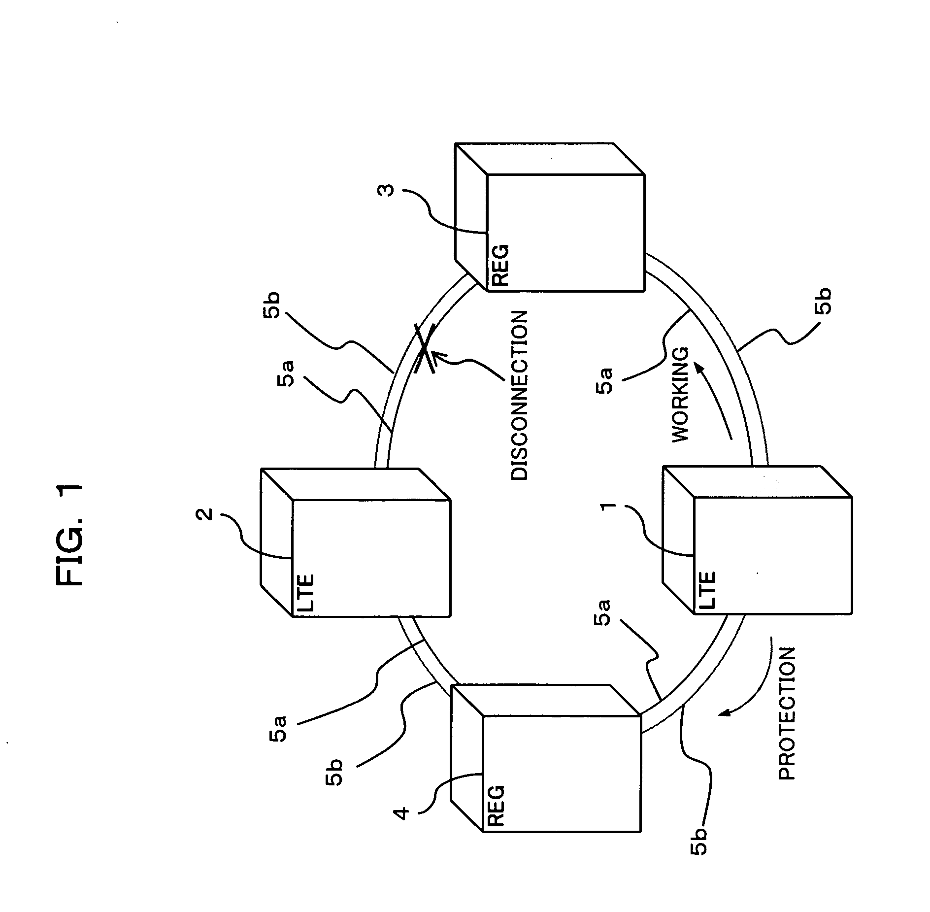
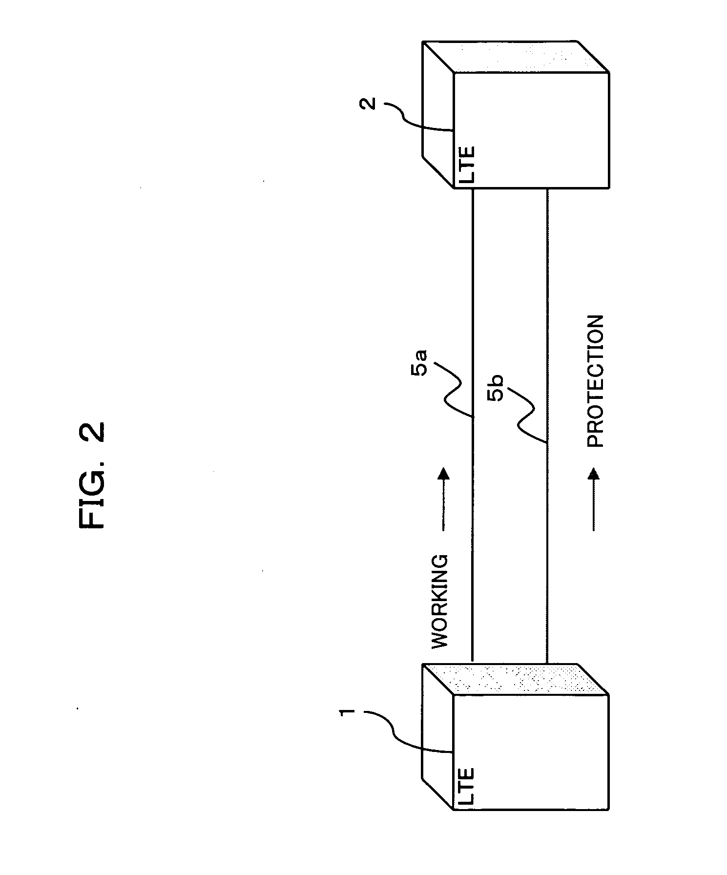
[0029]FIGS. 1 and 2 are block diagrams showing examples of an optical transmission system (network) according to a first embodiment of this invention. FIG. 1 shows a structure of an OUPSR network, while FIG. 2 shows a structure of a point-to-point network. The OUPSR network shown in FIG. 1 is configured by connecting, for example, two terminal node apparatuses (LTE: Lite Terminating Equipment) 1 and 2, and two regenerating apparatuses (Regenerators) 3 and 4 are connected through two optical transmission lines (optical fibers) 5a and 5b to form a ring network. In which, the same signal light is transmitted from the LTE 1, which is a transmitting end of the signal light, in both directions (namely, toward the regenerating apparatuses 3 and 4) through the different optical transmission lines 5a and 5b (of the working system and the protection system), while the LTE 2, which is a receiving end of the signal light, receives the signal light from the bot...

second embodiment

[2] Description of Second Embodiment

[0062]FIG. 7 is a block diagram showing a structure of a receiving side LTE according to a second embodiment of this invention. The LTE 2 shown in FIG. 7 has a structure differing from the structure shown in FIG. 3 in that two dispersion compensators (tunable dispersion compensators) 22a and 22b are connected to inputs of the optical switch 21 through optical fibers 7 correspondingly to the working system and the protection system, the input of the optical receiver 23 is connected to the output of the optical switch 21 through an optical fiber 8, and memories 27a and 27b for storing dispersion compensation quantities are provides for the working system and the protection system, respectively, as the above memory 27 for storing dispersion compensation quantities. Incidentally, other structural elements (designated by like or corresponding characters) are identical or similar ones that have been described hereinbefore unless otherwise specifically m...

third embodiment

[3] Description of Third Embodiment

[0070]FIG. 8 is a block diagram showing a structure of a receiving side LTE according to a third embodiment of this invention. The LTE 2 shown in FIG. 8 has a structure differing from the structure shown in FIG. 8 in that photodiodes 20a and 20b as being light receiving elements are connected to two inputs of the optical switch 21, and an optical receiver 28 and an optical switch controlling unit 29 are provided in place of the monitoring LSI 24, the memory 25 and the TTI comparing unit 26. In FIG. 8, like reference characters designate like or corresponding parts described above unless otherwise specifically mentioned.

[0071] The PD 20a receives the received signal light from the optical transmission line 5a of the working system, and outputs an electric signal obtained according to the quantity of the received signal light to the dispersion compensation controlling unit 229 in the dispersion compensator 22. The PD 20b receives the received signal...


PUM


Abstract

An optical receiving apparatus has a route change detector for detecting occurrence of a route change of received signal light, a memory for beforehand storing optimum dispersion compensation quantity for the received signal light before and after the route change, a tunable dispersion compensator for compensating dispersion of the received signal light, and a controller for controlling a dispersion compensation quantity used by the tunable dispersion compensator according to the optimum dispersion compensation quantity for the received signal light after the route change, which is beforehand stored in the memory, when the route change detector detects occurrence of the route change. The dispersion compensation quantity can be optimized at high-speed for each of optical transmission routes of the received signal light.

Description

CROSS REFERENCE TO RELATED APPLICATIONS [0001] This application is based on and hereby claims priority to Japanese Application No. 2005-280400 filed on Sep. 27, 2005 in Japan, the contents of which are hereby incorporated by reference. BACKGROUND OF THE INVENTION [0002] (1) Field of the Invention [0003] The present invention relates to an optical receiving apparatus and a dispersion compensating method in the optical receiving apparatus. Particularly, the present invention relates to a technique suitable for dispersion compensation in a receiving terminal in large-capacity optical transmission at 40 Gbps, for example. [0004] (2) Description of Related Art [0005] A patent document 1 below has proposed a technique in relation with an optical receiver which can perform dispersion compensation in an optical communication system in which the routing of an optical transmission line is changed. The optical receiver disclosed in the patent document 1 estimates a total dispersion quantity fr...

Claims


Application Information

Patent Timeline
Patent Type & Authority Applications(United States)
IPC IPC(8): H04B10/12H04B10/2507H04B10/032H04B10/2513
CPCH04B10/25133H04J14/0227H04J14/0241H04J14/0283H04J14/0294H04J14/0279
Inventor OZAKI, MASAKAZUFUKUMITSU, KATSUMI
Owner FUJITSU LTD
Why Eureka
Try Eureka