
Methods of forming a recessed gate

a gate and recessed technology, applied in the field of gate forming, can solve the problems of channel length reduction, channel length reduction, operation defect,

Active Publication Date: 2007-03-29
SAMSUNG ELECTRONICS CO LTD
View PDF3 Cites 5 Cited by
  • Summary
  • Abstract
  • Description
  • Claims
  • Application Information

AI Technical Summary

Benefits of technology

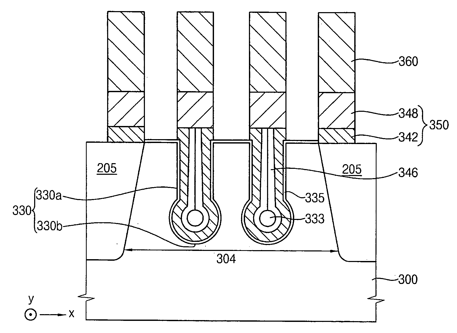
[0013] It is therefore a feature of embodiments of the invention to provide a method of forming a recessed gate wherein an operational defect due to a void within a gate electrode may be reduced and / or prevented.
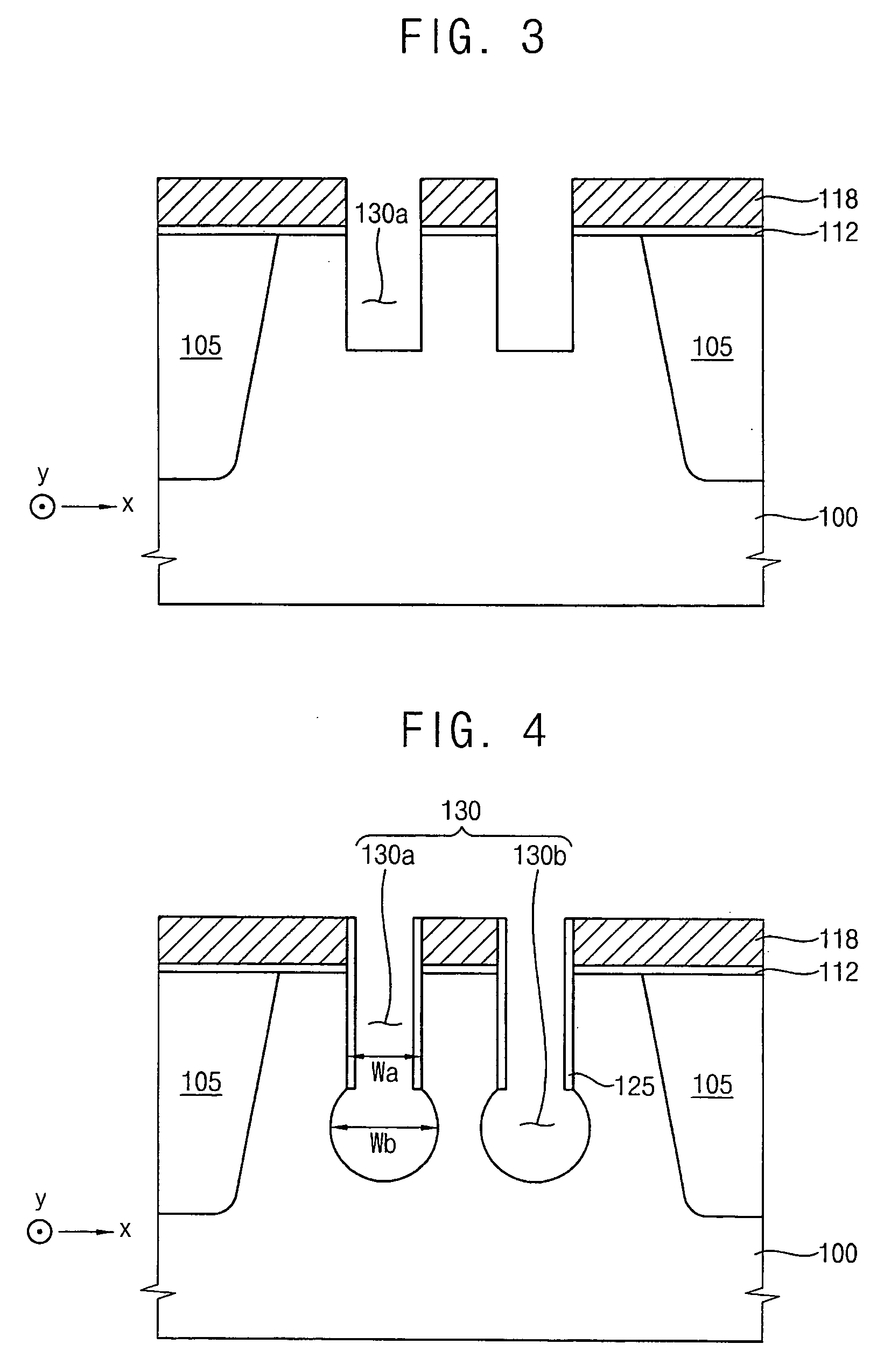
[0014] It is therefore a separate feature of embodiments of the invention to provide a method for preventing a void from being generated during formation of a gate electrode filled into a gate recess having a lower portion wider than the upper portion.
[0015] It is therefore a separate feature of embodiments of the invention to provide a method for forming a recessed gate, wherein movement of the void may be prevented even though the void may be generated during formation of the gate electrode.
[0016] It is therefore a separate feature of embodiments of the invention to provide a method for forming a recessed gate that enables the gate electrode to maintain contact with a gate insulation layer, irrespective of whether a void is formed during formation of the gate electrode, so that a leakage current may not be generated and that a threshold voltage distribution may not be deteriorated.

Problems solved by technology

The reduction of the gate size may result in a decrease of a channel length.
A reduction of the channel length may cause, via the short channel effect, an operational defect, e.g., a dynamic refresh defect or a static refresh defect.
However, filling up the gate recess without a void is generally difficult because of a small width of the gate recess.
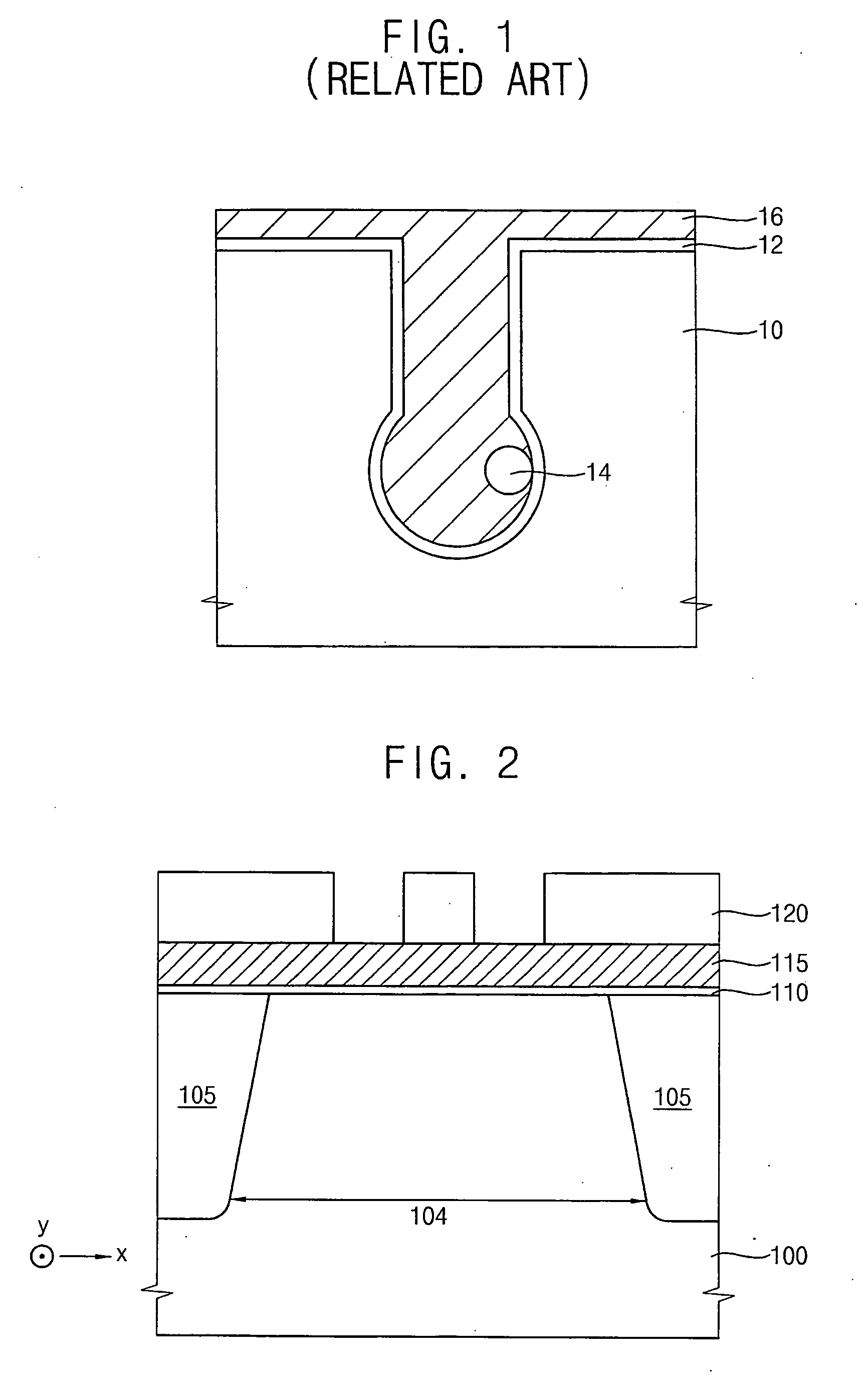
However, in such transistors with a gate recess having a relatively wider lower portion, an opening of the gate recess may be closed before the wider lower portion of the gate recess is sufficiently filled with a conductive material, and a void may be formed in the gate recess.
However, the void may move in the gate recess and may make contact with the gate insulation layer during subsequent processing, and electrical characteristics of the transistor may be deteriorated.
Thus, electrical characteristics of the MOS transistor may be deteriorated, and a production yield of a semiconductor device may be reduced.

Method used


Image

  • Methods of forming a recessed gate
  • Methods of forming a recessed gate
  • Methods of forming a recessed gate

Examples


Embodiment Construction

[0027] Korean Patent Application No. 2005-89074 filed on Sep. 26, 2005, in the Korean Intellectual Property Office, and entitled: “Method of Forming a Recessed Gate,” is incorporated by reference herein in its entirety.

[0028] The invention will now be described more fully hereinafter with reference to the accompanying drawings, in which example embodiments of the invention are illustrated. The invention may, however, be embodied in different forms and should not be construed as limited to the embodiments set forth herein. Rather, these embodiments are provided so that this disclosure will be thorough and complete, and will fully convey the scope of the invention to those skilled in the art.

[0029] In the figures, the dimensions of layers and regions may be exaggerated for clarity of illustration. It will also be understood that when a layer or element is referred to as being “on” another layer or substrate, it can be directly on the other layer or substrate, or intervening layers m...


PUM


Abstract

A method of forming a recessed gate may include forming a gate recess including an upper recess and a lower recess at an upper portion of a semiconductor substrate, the lower recess may have a width substantially wider than that of the upper recess, forming a gate insulation layer on an inner surface of the gate recess, forming a first silicon layer on the semiconductor substrate including the gate insulation layer to form an open void within the gate recess, forming a stop layer having a high thermal resistance on the first silicon layer to prevent a void from moving around within the gate recess, forming a second silicon layer on the first silicon layer, and patterning the second and the first silicon layers to form a gate electrode.

Description

BACKGROUND OF THE INVENTION [0001] 1. Field of the Invention [0002] The invention relates to a method of forming a gate. More particularly, the invention relates to a method of forming a gate in a recess that includes a lower portion that is substantially wider than an upper portion. [0003] 2. Description of the Related Art [0004] As semiconductor devices become highly integrated, active regions of semiconductor devices and various conductive structures formed on the active region(s) are decreasing in size. Accordingly, channel lengths of metal-oxide semiconductor (MOS) transistors may be less than several micrometers. [0005] As a channel length of a MOS transistor becomes shorter, voltages applied to source, drain and / or channel regions of the MOS transistor, have a larger influence on an electric field. This phenomenon is often called “a short channel effect.” As a result of the short channel effect, e.g., a threshold voltage may drop because the channel region may be affected not...

Claims


Application Information

Patent Timeline
Patent Type & Authority Applications(United States)
IPC IPC(8): H01L21/8242H01L21/20
CPCH01L29/66621H01L27/10876H10B12/053H01L29/4236H10B12/34
Inventor PARK, JIN-JUN
Owner SAMSUNG ELECTRONICS CO LTD
Learn More