Lens drive apparatus

a technology of drive apparatus and lens, which is applied in the direction of mountings, optics, instruments, etc., can solve the problems of variable position accuracy of lens and operational defects, and achieve the effects of preventing load concentration, preventing cam member deformation, and maintaining part accuracy

Inactive Publication Date: 2010-09-07
SEIKO PRECISION CO LTD
View PDF5 Cites 1 Cited by
  • Summary
  • Abstract
  • Description
  • Claims
  • Application Information

AI Technical Summary

Benefits of technology

[0009]It is therefore an object of the present invention to provide a lens drive apparatus, in which the accuracy of the parts is maintained, and the variation in the positional accuracy of the lens and the operational defect are prevented.
[0011]This configuration prevents the concentration of the load, applied to the holder at the time when the lens frame is assembled into the holder, on the cam member. Thus, it is possible to prevent the deformation of the cam member and to maintain the part accuracy. This prevents the variation, caused by the cam member, in the positional accuracy of the holder in the optical axis direction. This also suppresses the occurrence of defective operation of the holder.

Problems solved by technology

As a result, the variation in the positional accuracy of the lens and the operational defect might occur.

Method used


Image

  • Lens drive apparatus
  • Lens drive apparatus
  • Lens drive apparatus

Examples


Embodiment Construction

[0018]In the following, a description will be given of an embodiment according to the present invention with reference to the drawings.

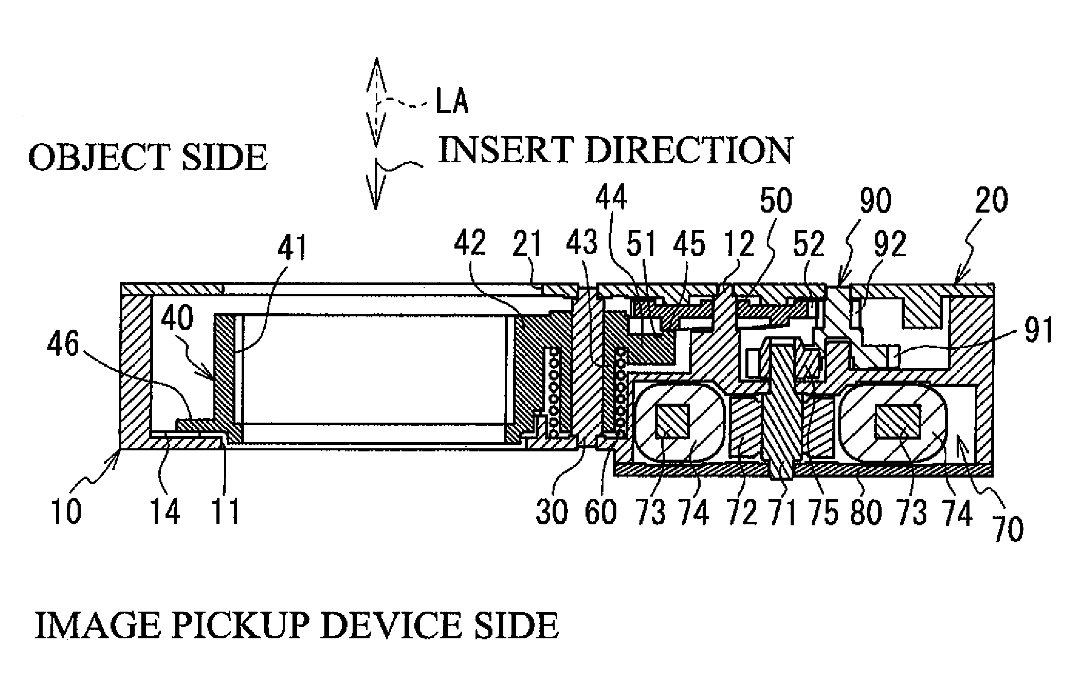
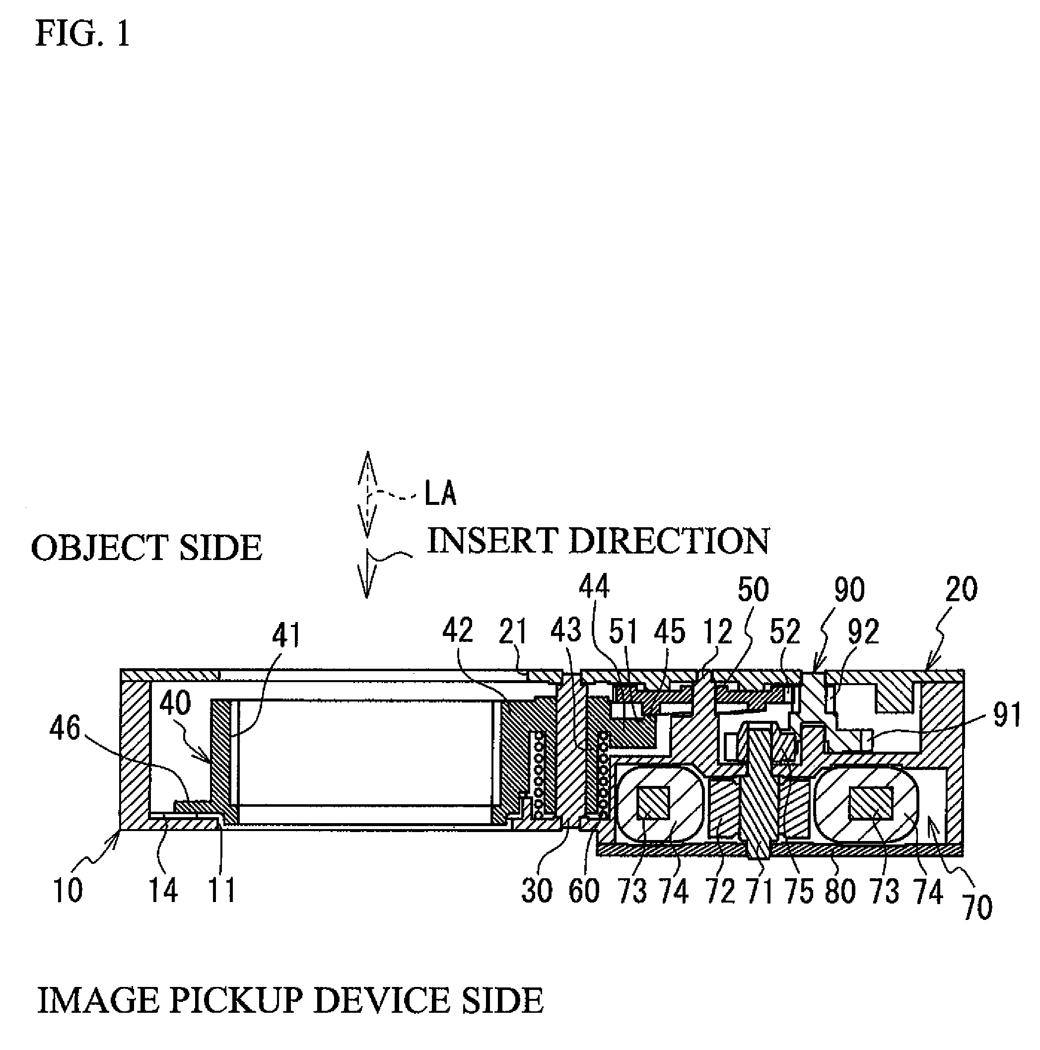
[0019]FIG. 1 is a cross-sectional view of a lens drive apparatus according to the present embodiment of the present invention.

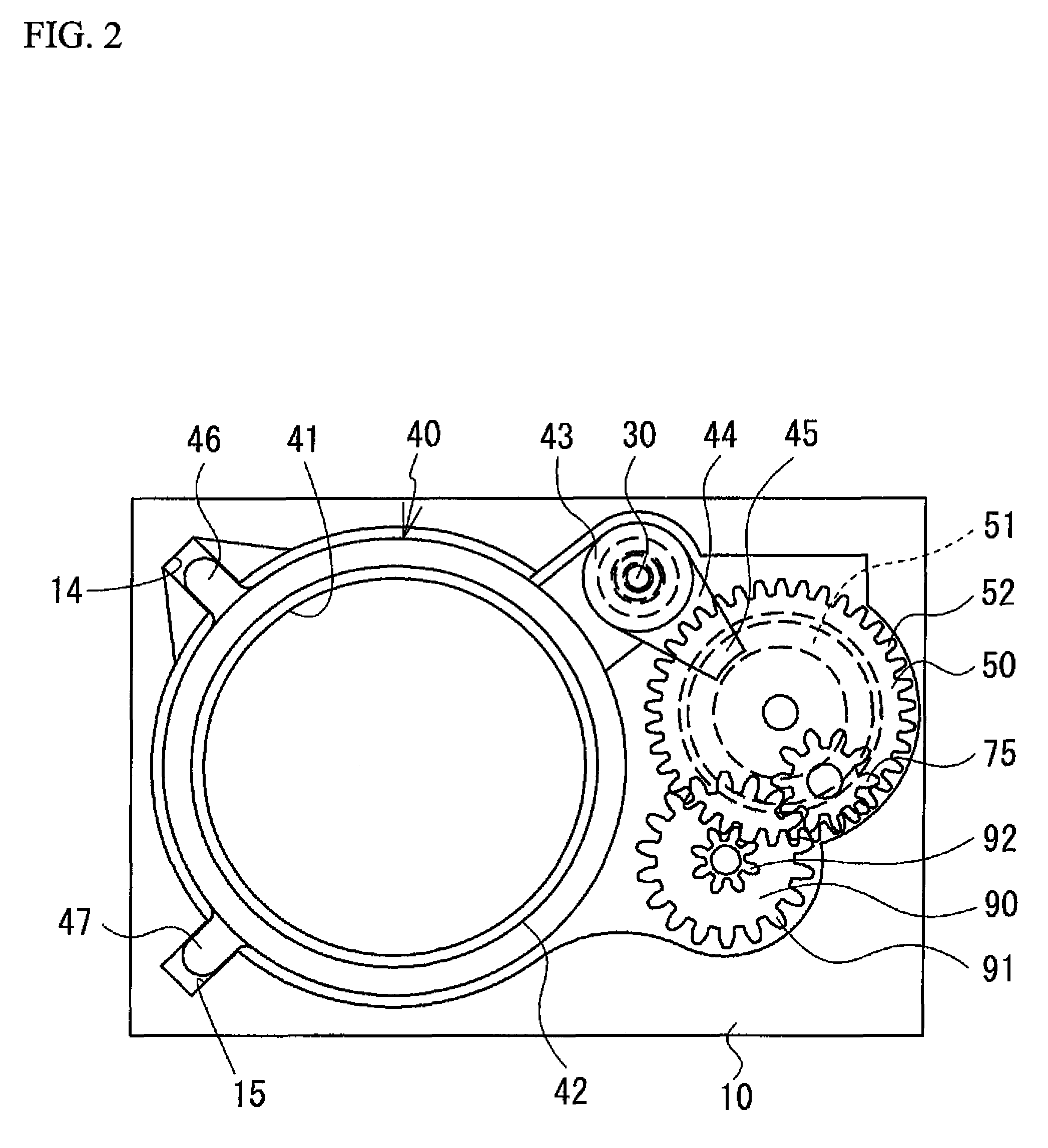
[0020]The lens drive apparatus includes: a base member 10; a cover member 20; a guide rod 30; a holder 40; a cam member 50; a biasing member 60; a motor unit 70; a plate 80; and a gear 90. Herein, in FIG. 1, the upper side is an object side and the lower side is an image pickup device side, the image pickup device (not shown) imaging the objective light.

[0021]The base member 10 and the cover member 20 define a housing holding the guide rod 30, the holder 40, the cam member 50, the biasing member 60, the motor unit 70 or the likes.

[0022]The base member 10 has an opening 11. The cover member 20 has an opening 21.

[0023]The guide rod 30 is supported so as to be parallel with the optical axis direction LA by the base member 10 and ...


PUM


Abstract

A lens drive apparatus includes: a base member; a holder having a cylindrical shape and movably supported in an optical axis direction relative to the base member; a cam member and moving the holder in the optical axis direction by abutting with the holder; and a biasing member urging the holder such that the holder 40 comes into contact with the cam member 50. The holder is formed such that a lens frame holding a lens is inserted and assembled into the holder from one side of the holder to another side of the holder. The cam member is disposed close to the one side with respect to the holder.

Description

CROSS-REFERENCE TO RELATED APPLICATION[0001]This application is a continuation of and claims priority to International Patent Application No. PCT / JP2008 / 053032 filed on Feb. 22, 2008, which claims priority to Japanese Patent Application No. 2007-089447 filed on Mar. 29, 2007, subject matter of these patent documents is incorporated by reference herein in its entirety.BACKGROUND OF THE INVENTION[0002]1. Field of the Invention[0003]The present invention relates to a lens drive apparatus.[0004]2. Description of the Related Art[0005]Conventionally, there has been known a lens drive apparatus including a holder and a cam member. The holder is movably supported in the optical axis direction and hold a lens, and the cam member moves the holder in the optical axis direction (see Japanese Unexamined Patent Application Publication No. 2005-195678).[0006]There is known a lens drive apparatus into which a lens is assembled in situ. FIG. 5 is a cross-sectional view of the aforementioned conventi...

Claims


Application Information

Patent Timeline
Patent Type & Authority Patents(United States)
IPC IPC(8): G02B15/14
CPCG02B7/08
Inventor KATSUMATA, MINORUKAWAMOTO, HISASHI
Owner SEIKO PRECISION CO LTD
Why Eureka
Try Eureka