Retractable safety syringe

a safety syringe and syringe technology, applied in the direction of intravenous devices, etc., can solve the problems of large imperfection rate, inability to reduce manufacturing costs, contamination and germ infection, etc., and achieve the effect of preventing damage to the breakage part of the barrel

Inactive Publication Date: 2007-03-29
ACXING INDAL CO LTD
View PDF8 Cites 24 Cited by
  • Summary
  • Abstract
  • Description
  • Claims
  • Application Information

AI Technical Summary

Benefits of technology

[0006] The present invention is to provide a retractable safety syringe, in order to facilitate retracting a needle after taking an injection, and to enable an easier manufacturing for reducing an imperfection rate and a cost.
[0008] The bore located at the inner rim of bottom end of barrel exit in the aforementioned syringe structure is a sheet whose center is provided with a threaded opening, and a slant stage member is located at a bottom edge of the bolt of push rod, such that the bolt can be properly rotated after entering the opening of the sheet, so as to be locked on the sheet, for facilitating a retraction of the push rod. Furthermore, as the needle being retracted is in a slant condition by the stage member, the syringe can be prevented from being recycled and causing contamination.
[0010] In the aforementioned syringe, a ring of groove is located on a surface of the barrel at a position close to an end, such that a cover having a through-hole in a center and a latching hooks at sides can be covered on the end and latched into the groove with the latching hooks, thereby forming a restrain to the end for preventing damage to the breakage part of the barrel upon taking an injection.

Problems solved by technology

As the entire structure of syringe remains intact, there is a doubt that the syringe will be recycled by unworthy people during a process of destroying, thereby causing contamination and germ infection.
Therefore, an issue of precision between these two compartments occurs, which induces a trouble to mass production, thereby causing a large imperfection rate, and an inability of reducing a manufacturing cost.
Accordingly, they are not able to be utilized generally, which is very imperfect.

Method used


Image

  • Retractable safety syringe
  • Retractable safety syringe
  • Retractable safety syringe

Examples


Embodiment Construction

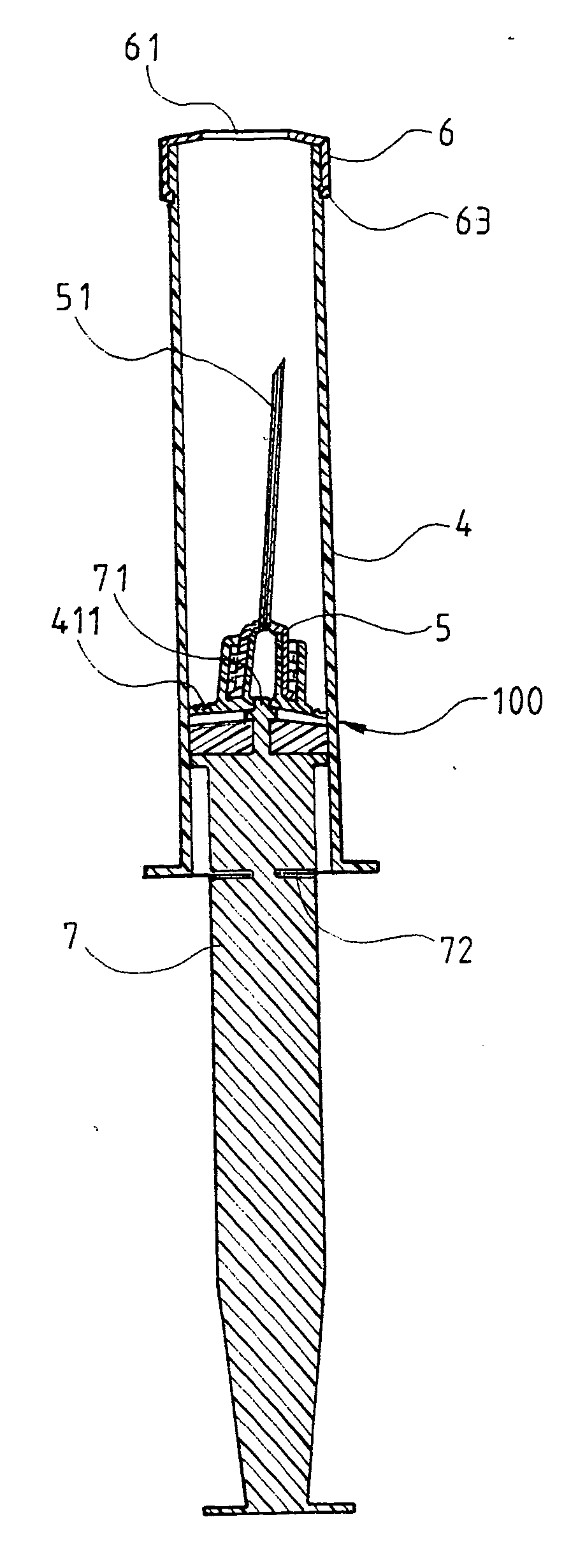
[0025] Referring to FIG. 4, FIG. 5, FIG. 6 and FIG. 6A, the present invention comprises primarily a barrel 4, a seat 5, a cover 6, and a push rod 7, wherein a tubular exit 42 is located at an end 41 of the barrel 4 for fixing the seat 5 having a needle 51, a sheet 43 is located at an inner rim of bottom of the exit 42, a circular bore 431 is located at a center of the sheet 43, a thin breakage part constituted by a groove in a continuous point shape is located at a periphery of the end 41 of the barrel 4, and a ring of groove 44 is located on a surface of the barrel 4 close to the end 41.

[0026] The cover 6 is in a shape of cap whose center is provided with a through-hole 61, whose sides are provided with notches 62, and whose inner rim at bottom of sides is provided with latching hooks 63, such that when the cover 6 is covered on the end 41 of the barrel 41, the latching hooks 63 at the bottom edge can be latched into the groove 44 on the barrel surface, and the seat 5 and the need...


PUM


Abstract

A retractable safety syringe includes primarily a barrel, a seat, and a push rod, wherein a tubular exit is located at an end of the barrel, a bore is located at an inner rim of bottom of exit, a thin breakage part is located at a periphery of the end, and a groove is located on a surface of barrel close to the end for latching and fixing a cover. A bolt is located at a top end of the push rod, so as to retract the push rod by locking the bolt of push rod into the bore at the inner rim of exit of barrel, after accomplishing an injection with the syringe, thereby breaking the breakage part at the periphery of barrel from a stretching force and retracting a needle into the barrel, in order to prevent the used syringe from being recycled.

Description

BACKGROUND OF THE INVENTION [0001] (a) Field of the Invention [0002] The present invention relates to a retractable safety syringe and more particularly to a syringe wherein a barrel will be broken and a needle will be retracted into the barrel by a retraction after taking an injection, so as to prevent the syringe from being recycled. [0003] (b) Description of the Prior Art [0004] For an ordinary syringe, as a needle is still fixed on a barrel after taking an injection, a common processing method is to separate the needle from the barrel, and destroy them separately. As the entire structure of syringe remains intact, there is a doubt that the syringe will be recycled by unworthy people during a process of destroying, thereby causing contamination and germ infection. Accordingly, some vendors have designed a variety of retractable syringes to retract needles into barrels to avoid reuse. As shown in FIG. 1, in the new patent 88211100, a needle 11 is provided with a latching structure...

Claims


Application Information

Patent Timeline
Patent Type & Authority Applications(United States)
IPC IPC(8): A61M5/00
CPCA61M2005/5073A61M5/322
Inventor LEE, SHUEI-YUANPEI, PEI-HSINHSUEH, TU-SING
Owner ACXING INDAL CO LTD
Why Eureka
Try Eureka