Method for repairing bone

a bone and bone technology, applied in the field of bone repair devices, can solve problems such as operative complications, and achieve the effect of good mechanical resistance of the structur

Inactive Publication Date: 2007-03-29
COUSIN BIOTECH R L
View PDF10 Cites 53 Cited by
  • Summary
  • Abstract
  • Description
  • Claims
  • Application Information

AI Technical Summary

Benefits of technology

[0013] For vertebrae, it is known to remove all or part of the vertebral body via an anterior route which leaves the necessary room for placing the tube in position filled with grafts or compressed bone fragments. The purpose of the plate is to maintain good mechanical resistance of the structure and to maintain the tube with the filler product within a precisely delimited zone between the bones while awaiting bone consolidation.

Problems solved by technology

However to place the rigid cage in position it is necessary to draw aside adjacent vertebrae which leads to operative complications.

Method used


Image

  • Method for repairing bone
  • Method for repairing bone

Examples


Embodiment Construction

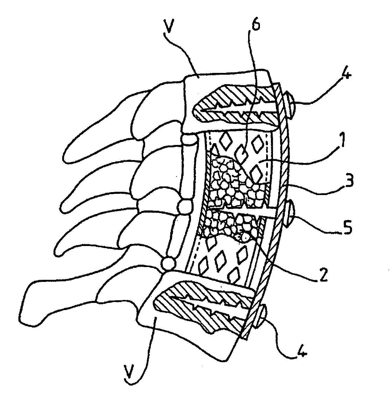
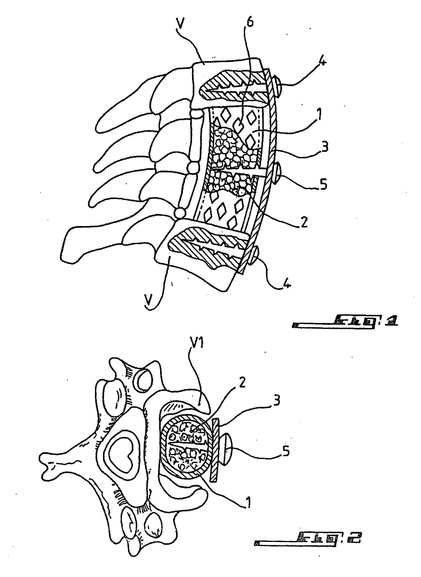
[0018] In the figures, the same reference numbers denote the same parts. In FIG. 1 it can be seen that the implant is formed by a substantially cylindrical tube 1 containing bone grafts 2, which is inserted between two healthy vertebrae V. A plate 3 is applied along the length of tube 1, the plate 3 being screwed into the vertebrae respectively above and below the vertebra which has undergone partial removal of the vertebral body. Plate 3 is held in position by securing screws 4 at its two ends, screws 4 being fixed in the two healthy vertebrae V. The implant is joined to plate 3 by at least one screw 5 which, in the example shown, is central. According to the invention, the wide meshes 6 clear after a certain time to allow growth of the grafts. Vertebral transverse and spinous processes (not referenced) can also be seen in this figure. FIG. 2 is an overhead view of the implant in position within a sectioned vertebral body V1. The medullary canal (not referenced) is schematised in t...


PUM

PropertyMeasurementUnit
flexibleaaaaaaaaaa
biocompatibleaaaaaaaaaa
shapeaaaaaaaaaa

Abstract

A method for repairing bone in a bone cavity delimited by healthy bone faces, and from which traumatized bone has been excised, comprises adjusting a flexible, biocompatible mesh fabric tube to fit the bone cavity and contact the healthy bone faces and filling the mesh tube with a bone graft. A bioresorbable coating is applied to the tube to rigidify the tube having been adjusted in shape to fit the bone cavity. The coating seals the mesh against graft movement through the mesh of the tube until the bioresorbable coating has been resorbed. The tube is inserted within the bone cavity and the coating is resorbed to allow the graft to pass from the interior of the tube, through the mesh, to the healthy bone faces.

Description

FIELD OF INVENTION [0001] The subject of the present invention is a device for bone repair by arthrodesis, intended to be used for the reconstitution of bone trauma, cervical vertebrae in particular. BACKGROUND [0002] During operations performed to treat bone diseases of the spine, the surgeon fully or partially excises one or more vertebral bodies. The mechanical support previously given by this excised bone is therefore no longer provided. To overcome this disadvantage, rods are known to be used, generally titanium, and the spaces left empty after bone removal are filled with an inert, biocompatible material. A rod is inserted between two healthy vertebrae to provide initial support until injected cement material has hardened. An autologous single block graft, a bone from a bone bank or even a bone substitute may also be used. [0003] Another technique consists of replacing the rod and biocompatible cement material by a rigid wired structure called a vertebral body, in which a bone...

Claims


Application Information

Patent Timeline
Patent Type & Authority Applications(United States)
IPC IPC(8): A61F2/44A61B17/70A61B17/58A61B17/80A61B17/86A61F2/00A61F2/02A61F2/28A61F2/30A61L27/00A61L31/00A61L31/06
CPCA61B17/7059A61B17/86A61L2430/02A61F2/2846A61F2/30767A61F2/44A61F2/4465A61F2002/2835A61F2002/30062A61F2002/30064A61F2002/30126A61F2002/30148A61F2002/30228A61F2002/30235A61F2002/30433A61F2002/30672A61F2002/30787A61F2002/30909A61F2210/0004A61F2220/0041A61F2230/0008A61F2230/0017A61F2230/0069A61L31/005A61L31/06C08L67/04
Inventor POINTILLART, VINCENTDENEUVILLERS, GUYMELIOT, SEBASTIEN
Owner COUSIN BIOTECH R L
Why Eureka
Try Eureka