Database and method of verifying function of LSI using the same

unction verification technology, applied in the field of database and a function verification method of a large-scale integrated circuit (lsi), can solve the problems of lsi verification or misunderstanding, the number of items to be verified by verification of a function of a lsi is increasing exponentially, and the contents of verification or misunderstanding are also increasing. to achieve the effect of easy verification of a function of a lsi

Inactive Publication Date: 2007-03-29
PANASONIC CORP
View PDF4 Cites 11 Cited by
  • Summary
  • Abstract
  • Description
  • Claims
  • Application Information

AI Technical Summary

Benefits of technology

[0007] The present invention is to solve the conventional problems, and it is an object of the present invention to easily verify a function of a LSI.

Problems solved by technology

Recently, as large scale or high integration of a LSI is progressing and a circuit arrangement becomes complicated, the number of items to be verified by verification of a function of the LSI is increasing exponentially and bug of the LSI due to omission of the function verification or misunderstanding of verified contents is also increasing.
Accordingly, omission or misunderstanding of the specification is caused and thus the verified items cannot be sufficiently verified or erroneous.
As the result, the verification of the function of the LSI may be omitted and a problem of the LSI may not be found.

Method used


Image

  • Database and method of verifying function of LSI using the same
  • Database and method of verifying function of LSI using the same
  • Database and method of verifying function of LSI using the same

Examples


first embodiment

(First embodiment)

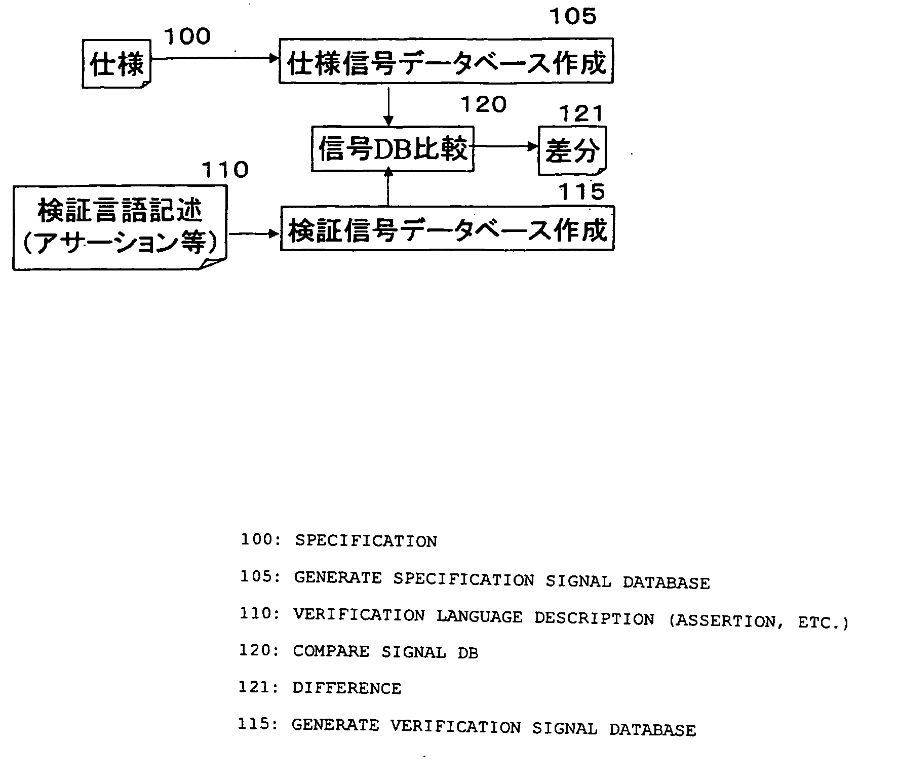
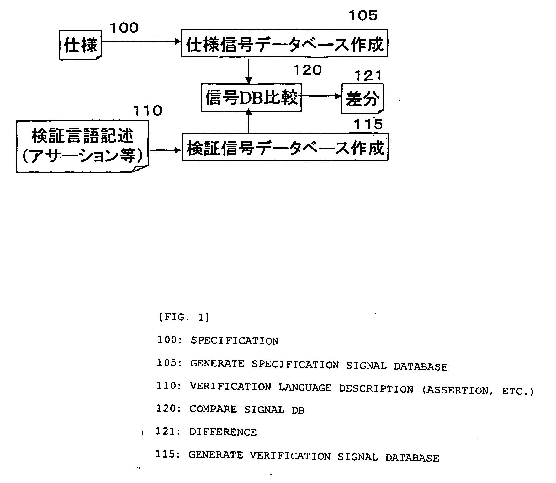
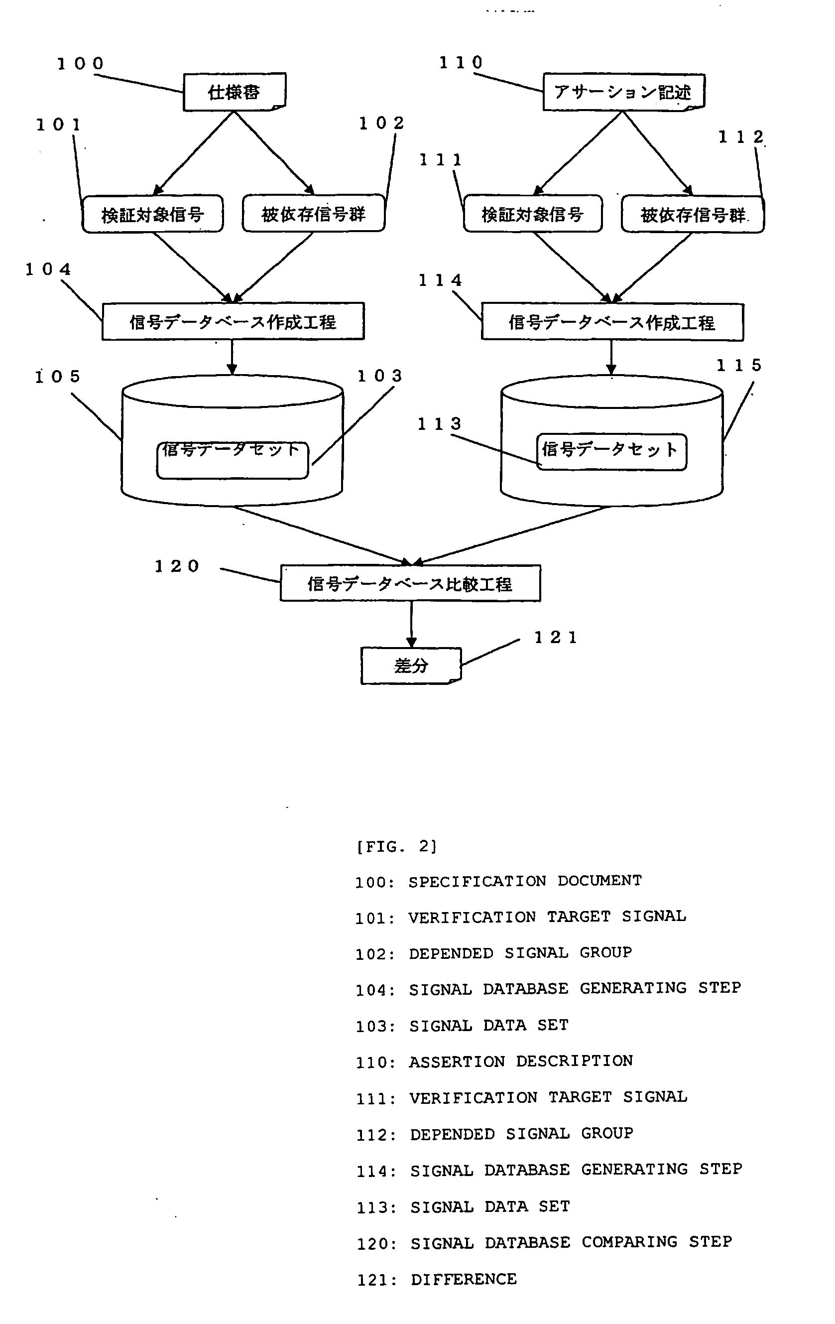
[0074] Hereinafter, a LSI function verifying method according to an embodiment (hereinafter, referred to as a first embodiment) of the present invention will be described with reference to the attached drawings. In the present embodiment, a verified signal related to a verifying signal is extracted from descriptions having different description rules and signal data sets which associate a verification target signal having a defined operation with a depended signal group which influences the operation of the verification target signal are generated, and databases for storing the signal data sets are used.

[0075] In the LSI function verifying method according to the present embodiment, by comparing the signal data sets are compared using the databases and determining whether there is a difference to detect omission or error of the description, matching is checked. In addition, it is checked whether the function is properly verified.

[0076]FIG. 1 is a view showing the...

second embodiment

(Second Embodiment)

[0088] Next, a database having delay time information will be described as a modified example of the database used herein. As shown in FIG. 5, by adding delay times required for changing depended signals B1, B2, . . . , and Bm and then reaching verification target signals A1, A2, . . . , and An, comparison can be performed in a time axis. In Figure, the time uses a predetermined unit time. By storing such a signal data set, the delay times are simultaneously compared. “ο” denotes that the depended signal directly has an influence on the operation of the verification target signal and “−” denotes does not have an influence on the operation of the verification target signal.

third embodiment

(Third Embodiment)

[0089] Next, a database having delay time information will be described as another modified example of the database used herein. As shown in FIG. 6, delay times required for changing depended signals B1, B2, . . . , and Bm and then reaching verification target signals A1, A2, . . . , and An are expressed by the number of the clock cycles and comparison is performed in a time axis by adding delay data Clk1,5, Clk1,6,. . . The delay data Clk1,5 denotes that a clock signal Clk1 is delayed by five cycles in the verification target signal and the delay data Clk1,6 denotes that the clock signal Clk1 is delayed by six cycles in the verification target signal. By storing such a signal data set, the delay times are simultaneously compared.


PUM


Abstract

Provided is a method of verifying the function of the LSI including: a first signal database generating step of registering a first signal data set for associating a first verification target signal of which the operation is defined as the specification of the LSI with a first depended signal group for influencing the operation of the first verification target signal; a second signal database generating step of registering a second signal data set for associating a second verification target signal which is described in a description language for verifying the function of the LSI and is a verification target with a second depended signal group for influencing the operation of the second verification target signal; and a signal database comparing step of comparing the first signal data set with the second signal data set and outputs a difference. By this method, it is possible to clearly associate each signal of a specification and an assertion description of the LSI or a HDL with a signal group for influencing the operation of the signal and to find a possibility that the verified item or the assertion description is omitted or a signal operation which was not included in the HDL or the defect of the specification document by comparing signal data sets registered in signal databases with each other.

Description

BACKGROUND OF THE INVENTION [0001] 1. Field of the Invention [0002] The present invention relates to a database and a method of verifying a function of a large-scale integrated circuit (LSI) using the same, and more particularly, to a method of efficiently verifying a function of a LSI. [0003] 2. Description of the Related Art [0004] Recently, as large scale or high integration of a LSI is progressing and a circuit arrangement becomes complicated, the number of items to be verified by verification of a function of the LSI is increasing exponentially and bug of the LSI due to omission of the function verification or misunderstanding of verified contents is also increasing. As a LSI function verifying device for solving such problems, a formal function verifying device which need not prepare a test pattern in addition to a function simulator is used. [0005] In a conventional LSI function verifying method, since the formal function verifying device is basically similar to the function ...

Claims


Application Information

Patent Timeline
Patent Type & Authority Applications(United States)
IPC IPC(8): G06F17/50
CPCG06F17/5022G06F30/33
Inventor NISHIDA, YOSHIHITOTAKEMURA, KAZUYOSHIMIZUNO, MASANOBUTADA, KAZUHITO
Owner PANASONIC CORP
Why Eureka
Try Eureka