Micro-electro-mechanical pressure sensor

a pressure sensor and micro-electromechanical technology, applied in the field of pressure sensors, can solve the problems of complex and susceptible to damage, high cost, and high cost of sensors, and achieve the effect of high quality

Inactive Publication Date: 2007-04-05
AHURA CORP
View PDF0 Cites 17 Cited by
  • Summary
  • Abstract
  • Description
  • Claims
  • Application Information

AI Technical Summary

Benefits of technology

[0013] More particularly, in one form of the invention, oscillation may be induced in the mass target, and the dampening effect of the gas molecules on the excited mass target may be observed: higher gas pressures will yield larger dampening effects.
[0014] And in another form of the invention, oscillation may be induced in the mass target and the additional excitation effect of the gas molecules impacting on the already excited mass target may be observed: higher gas pressures will yield larger additional excitation effects.
[0015] And in still another form of the invention, no external oscillation may be imputed to the mass target, and the excitation effect of the gas molecules impacting on the mass target may be observed: higher gas pressures will yield larger excitation effects.

Problems solved by technology

This makes sensor construction complicated and susceptible to damage when the sensor is subjected to pressures outside the intended measurement range.
However, both the thermocouple gauge and the ion gauge methods suffer from disadvantages.
The thermocouple gauge method is highly non-linear and has a limited dynamic range.
The ion gauge method can generally only be used at high levels of vacuum and will generally be damaged if turned on at higher pressures.
The ion gauge method also requires a high voltage electric source, which effectively prohibits its use in portable applications.

Method used


Image

  • Micro-electro-mechanical pressure sensor
  • Micro-electro-mechanical pressure sensor
  • Micro-electro-mechanical pressure sensor

Examples


Embodiment Construction

Theory of Operation

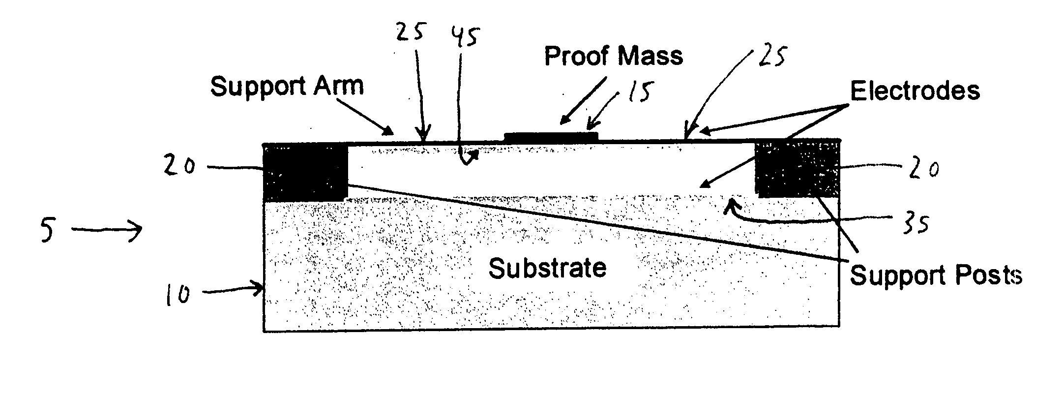
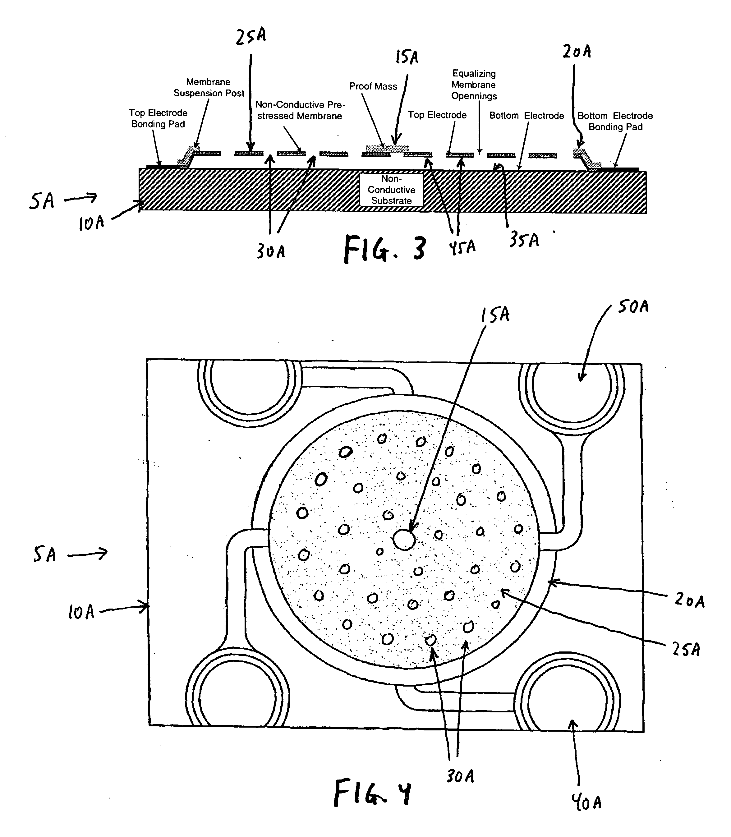
[0032] The mechanical portion of the pressure sensor has a mass target (also sometimes referred to herein as a “proof mass”) suspended on a spring structure, which together exhibit high Q (also sometimes referred to herein as “high quality”) mechanical resonance. The moving part of the pressure sensor has a mass M and an area A, where the area A is presented in a plane perpendicular to the direction of the mechanical oscillation of the structure. As the spring structure moves, it will elastically deform. The sensor measures pressure by characterizing the effects that gas molecules produce on the motion of the structure. This effect may be the damping of an oscillating structure that is externally excited; or it may be the excitation effect caused by the impact of gas molecules on the structure.

[0033] The pressure sensor may take the form of many different embodiments.

[0034] By way of example but not limitation, and looking now at FIGS. 1 and 2, there is shown a...


PUM

PropertyMeasurementUnit
pressureaaaaaaaaaa
pressureaaaaaaaaaa
pressureaaaaaaaaaa

Abstract

A pressure sensor is disclosed for measuring fluid pressure comprising a pressure sensing structure comprising a mass target suspended on a spring mechanism, wherein the mass target and the spring mechanism together exhibit high Q mechanical resonance, wherein the mass target has an area which is presented in a plane perpendicular to the direction of the mechanical oscillation of the structure, and further wherein the mass target and the spring mechanism are in the form of a membrane, and transducer means for measuring the fluid pressure by characterizing the effects that the fluid molecules produce on the motion of the structure.

Description

REFERENCE TO PENDING PRIOR PATENT APPLICATIONS [0001] This patent application claims benefit of: [0002] (1) pending prior U.S. Provisional Patent Application Ser. No. 60 / 440,154, filed Jan. 15, 2003 by Jakob Kogan et al. for MINIATURE RF / MEMS PRESSURE SENSOR (Attorney's Docket No. AHURA-4 PROV); and [0003] (2) pending prior U.S. Provisional Patent Application Ser. No. 60 / 534,089, filed Jan. 2, 2004 by Yakov Kogan for MICRO-ELECTRO-MECHANICAL VACUUM SENSOR (Attorney's Docket No. AHURA-17 PROV). [0004] The two above-identified patent applications are hereby incorporated herein by reference.FIELD OF THE INVENTION [0005] This invention relates to pressure sensors in general, and more particularly to micro-electro-mechanical pressure sensors. BACKGROUND OF THE INVENTION [0006] Gas pressure is a measure of the mechanical interaction of gas molecules with the surface of an object placed in that gas. Gas pressure is proportional to molecular concentration and gas temperature. [0007] Methods...

Claims


Application Information

Patent Timeline
Patent Type & Authority Applications(United States)
IPC IPC(8): G01L11/00G01L21/22
CPCG01L21/22
Inventor KOGAN, YAKOVVAKHSHOORI, DARYOOSHWANG, PEIDONG
Owner AHURA CORP
Why Eureka
Try Eureka