

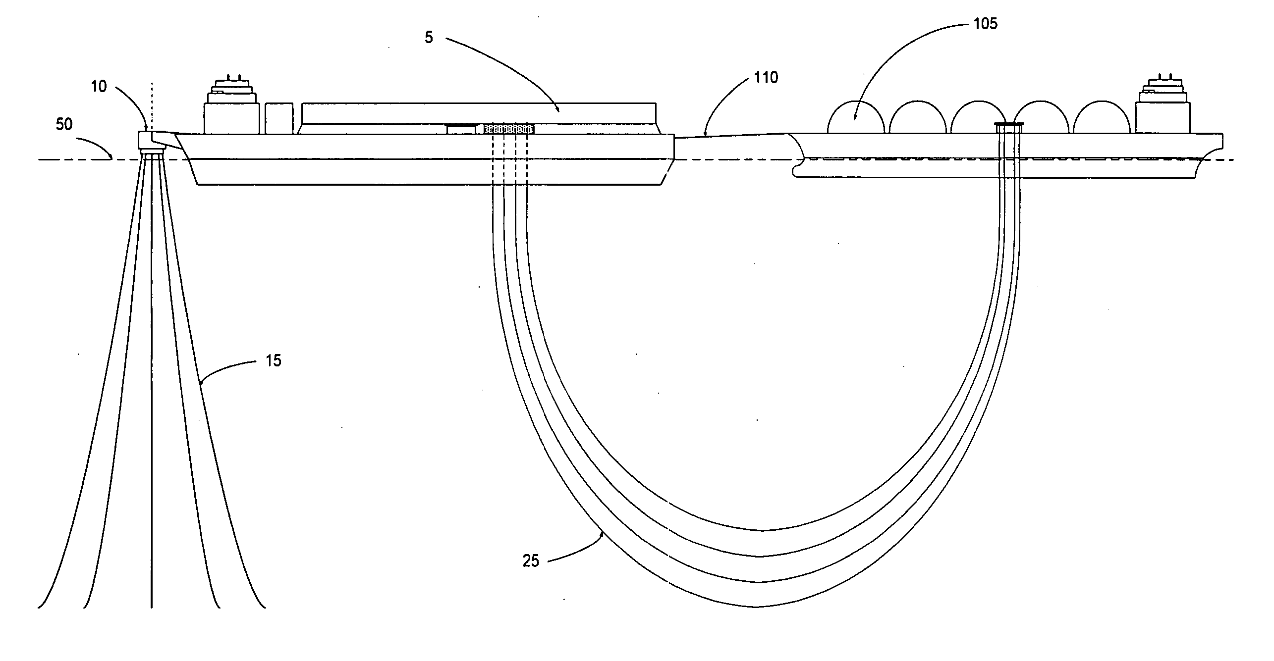
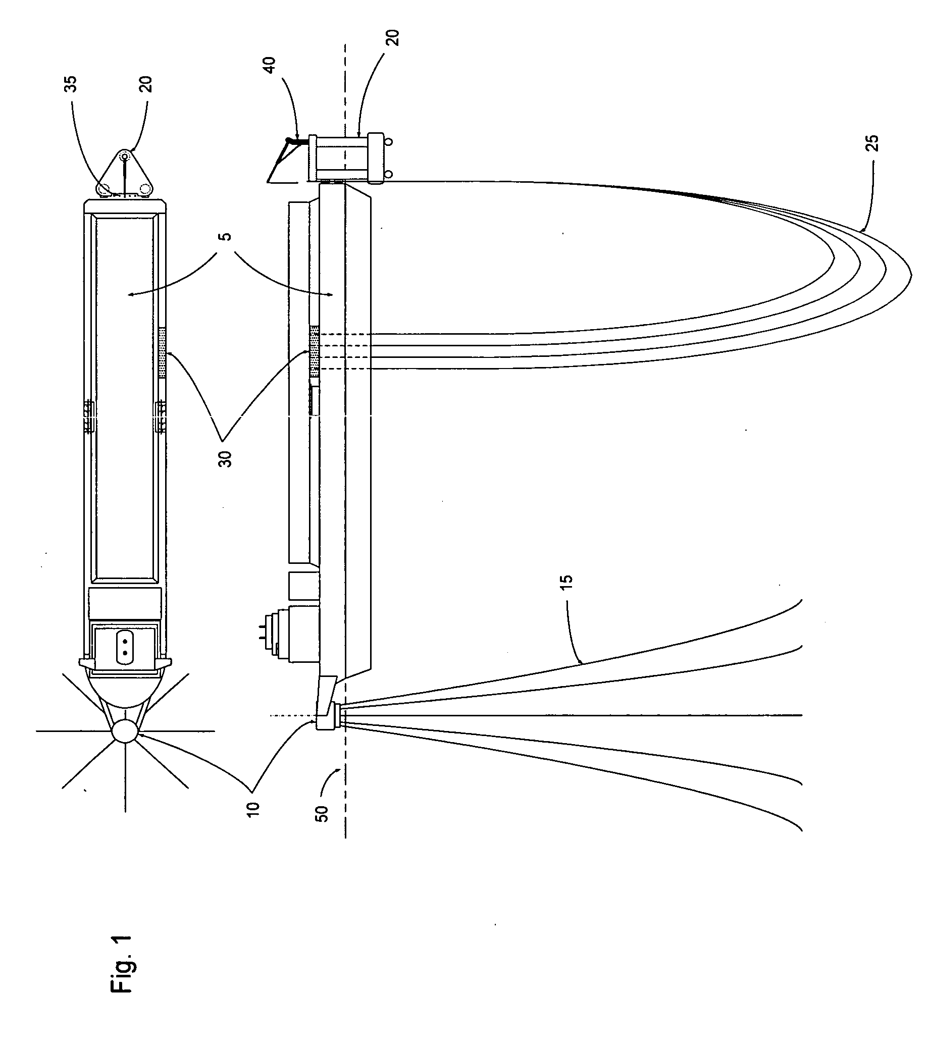
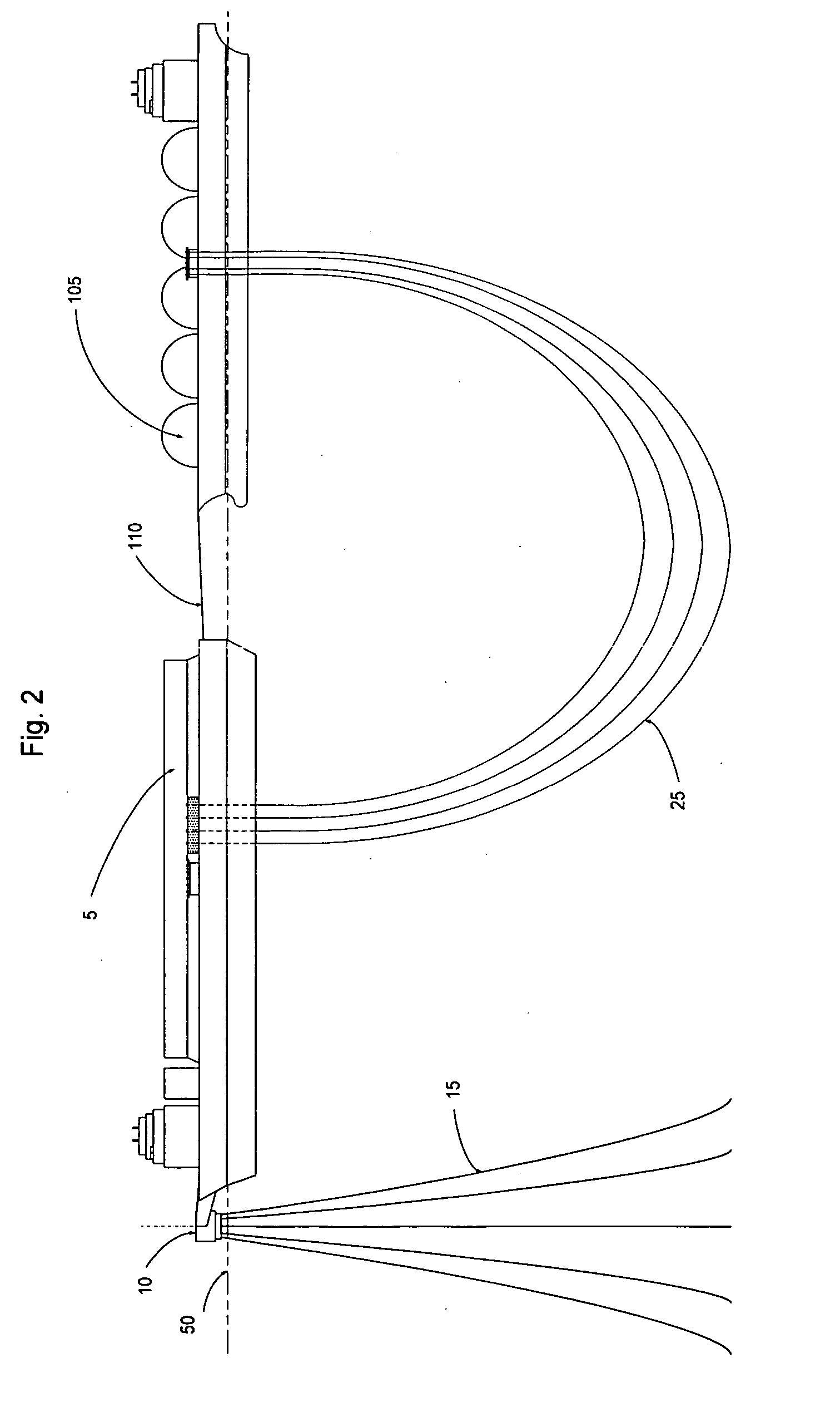
System using a catenary flexible conduit for transferring a cryogenic fluid
a flexible conduit and fluid transfer technology, applied in the direction of special-purpose vessels, container discharging methods, packaging goods types, etc., can solve the problems of unprotected locations, high risk to personnel safety, and inability to transfer cryogenic fluids in open ocean in unprotected locations, so as to minimize any required modifications to the vessel, improve the safety of the fluid transfer system
- Summary
- Abstract
- Description
- Claims
- Application Information
AI Technical Summary
Benefits of technology
Problems solved by technology
Method used
Image

Examples
Embodiment Construction
[0027] The present invention is directed to a flexible conduit system comprising a flexible conduit. In this disclosure, the terms conduit means, conduit, pipe and hose are used interchangeably in reference to the conduit means of this invention. For purposes of this disclosure, these terms are deemed to be equivalent, unless otherwise indicated.
[0028] For purposes of this disclosure, a cryogenic fluid is a liquid phase fluid which must be maintained at sub-ambient temperatures (i.e. temperatures less than 25° C.) and / or at a super-ambient pressure (i.e. at a pressure greater than 15 psia) to remain in the liquid phase. Liquefied natural gas (LNG) is a cryogenic fluid comprising predominately methane with decreasing amounts of C2+ hydrocarbons. Liquefied heavy gas (LHG) is a cryogenic fluid comprising predominately C2+ hydrocarbons. Liquefied petroleum gas (LPG) is a cryogenic fluid comprising predominately C3+ hydrocarbons. Any or all of these fluids, when maintained in the cryoge...
PUM
| Property | Measurement | Unit |
|---|---|---|
| Pressure | aaaaa | aaaaa |
| Flexibility | aaaaa | aaaaa |
Abstract
Description
Claims
Application Information