

Heat exchanger
a technology of heat exchanger and heat exchange core, which is applied in the direction of indirect heat exchanger, lighting and heating apparatus, refrigeration components, etc., can solve the problems of reducing the flow rate of refrigerant, uneven air passing through the heat exchange core at different locations, and so as to reduce the number of components. , the effect of reducing the number of components
Inactive Publication Date: 2007-04-05
KEIHIN THERMAL TECH CORP
View PDF4 Cites 30 Cited by
- Summary
- Abstract
- Description
- Claims
- Application Information
AI Technical Summary
Benefits of technology
[0053] With the heat exchangers described in par. 1) and 2), the end portions of the heat exchange tubes inserted in the inflow header project outward beyond the refrigerant passing holes of the partitioning means longitudinally of the tubes, so that the refrigerant portions flowing into the inflow header from the tubes pass over the outer edges, in the longitudinal direction, of the tubes, flow into the outflow header through the holes and are thereby mixed together. Moreover, the refrigerant flowing into the inflow header is unlikely to pass directly through the holes, therefore partly flows inside the inflow header also longitudinally thereof and is agitated at this time. Accordingly, when used as an evaporator, for example, the heat exchanger efficiently mixes the liquid-phase refrigerant portion and the vapor-phase refrigerant portion to result in a generally uniform quality of wet vapor, giving a generally uniformalized temperature to the air passing through the heat exchange core and realizing an improved refrigeration efficiency, i.e., heat exchange efficiency.
[0079] The heat exchanger described in par. 38) can be smaller in the number of components, and can be provided with the partitioning means in the tank with ease.
Problems solved by technology
However, various studies conducted by the present inventor have revealed that the following problems are likely to arise owing to the structure of the evaporator disclosed in the above publication wherein the lower ends of the two groups are positioned above the lower ends of the refrigerant passing holes.
Consequently, the liquid-phase refrigerant and the vapor-phase refrigerant can not be efficiently mixed together inside the inflow header and inside the outflow header, and the air passing through the heat exchange core becomes uneven at different locations.
The refrigerant not vaporized completely has a lower temperature, which is detected by the expansion value, which in turn diminishes its valve opening, reducing the rate of flow of the refrigerant and resulting in a larger region of superheat.
The superheat region of increased area involving inefficient heat exchange leads to impaired refrigeration performance.
We have found that this position of the inlet and outlet is likely to give rise to the following problems.
For this reason, the paths of flow of the refrigerant through the evaporator become uneven in length, resulting in an uneven pressure distribution and permitting the refrigerant to flow through all the heat exchange tubes at varying rates.
As a result, the air passing through the heat exchange core becomes uneven at different locations.
Thus, the amount of refrigerant contributing to heat exchange becomes uneven with respect to the left-right direction of the heat exchange core, with the result that the air passing through the core becomes also uneven in temperature at different locations.
The inflow header and the outflow header therefore fail to efficiently mix together the liquid-phase refrigerant and the vapor-phase refrigerant therein, giving the air passing through the core a temperature varying with the location.
Method used
View moreImage
Smart ImageViewing Examples

Examples
example 1
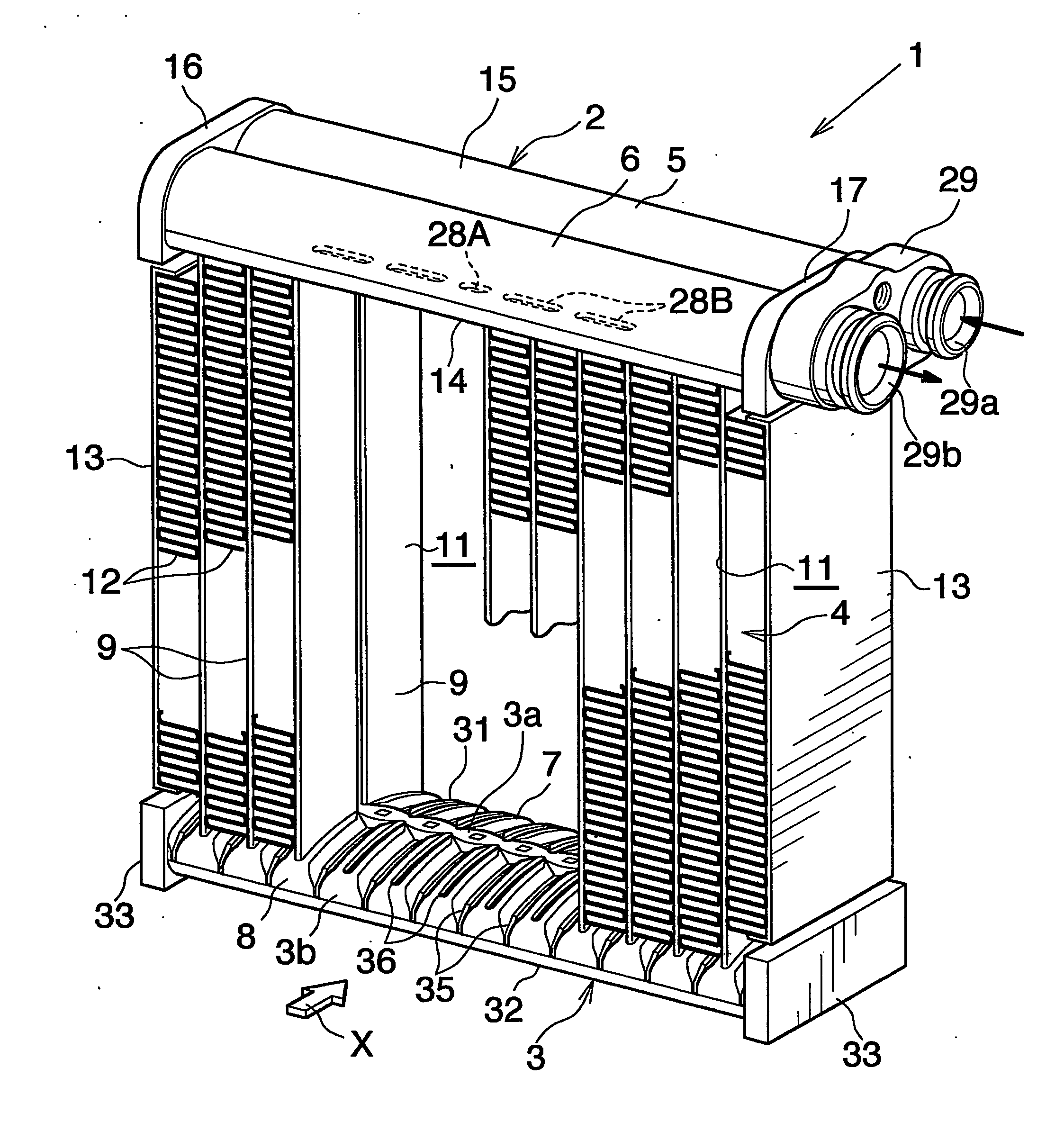
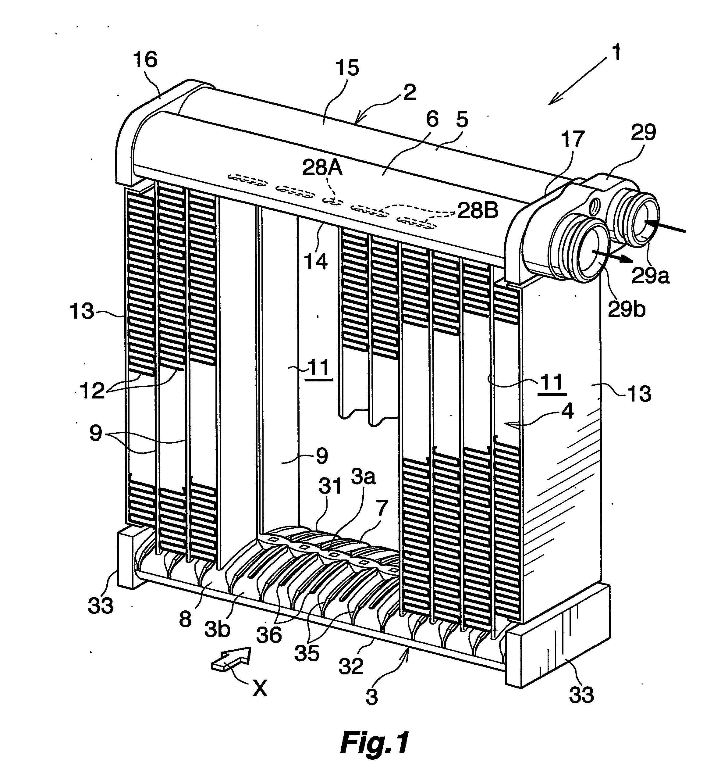
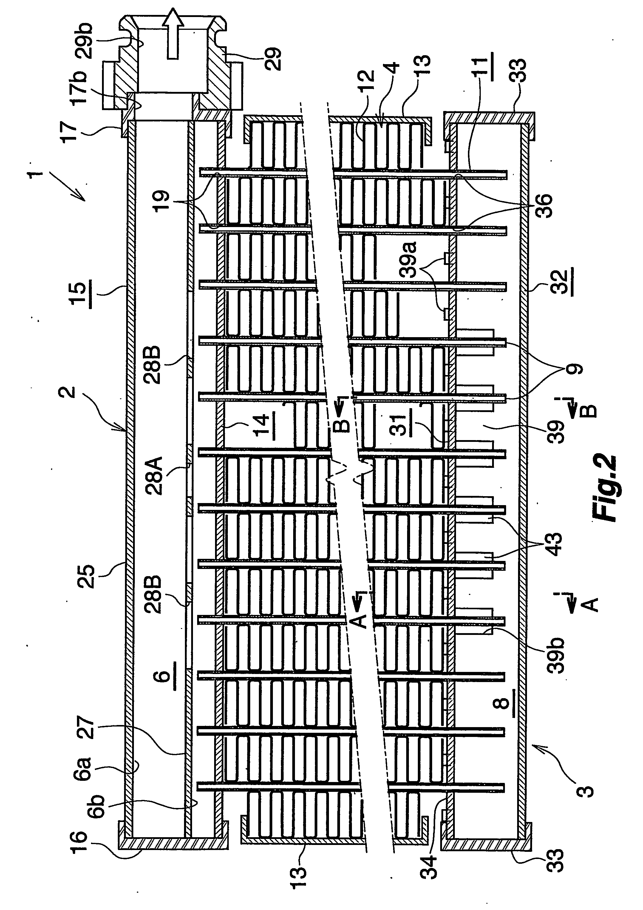
[0164] The evaporator shown in FIGS. 10 to 13 was used. The heat exchange core 4 measured 255 mm in lateral width and 38 mm from front to back, the heat exchange tubes 9 of each tube group 11 were 26 in number, 1.4 mm in height and 17.7 mm in width, and the corrugated fins 12 were 3.3 mm in fin pitch and 8 mm in height. The refrigerant passing holes 81 in the flow dividing resistance plate 27 were 13 in number. The temperature distribution of the air forced out from the front side of the heat exchange core 4 was measured according to JIS D1618. FIG. 15 shows the result.
Login to View More PUM
 Abstract
A heat exchanger comprising a heat exchange core 4 composed of tube groups 11 in the form of rows arranged in the direction of flow of air through the exchanger, each of the tube groups 11 comprising a plurality of heat exchange tubes 9 arranged at a spacing, a refrigerant inlet header 5 and a refrigerant outlet header 6 positioned at the upper end of the core 4 and having respective groups of heat exchange tubes joined thereto, and a refrigerant turn tank 3 disposed at the lower end of the core 4. The turn tank 3 has its interior divided by a partition wall 39 into a refrigerant inflow header 7 and a refrigerant outflow header 8. The heat exchange tubes 9 have lower end portions inserted in the headers 7, 8 and are joined to the headers 7, 8. Refrigerant passing holes 43 are formed in the partition wall 39. The heat exchange tubes 9 have their lower ends positioned below the lower ends of the holes 43. The heat exchanger is improved in heat exchange performance.
Description
CROSS REFERENCE TO RELATED APPLICATIONS [0001] This application is an application filed under 35 U.S.C. §111 (a) claiming the benefit pursuant to 35 U.S.C. §119(e) (1) of the filing date of Provisional Applications No. 60 / 518,308, No. 60 / 530,263 and No. 60 / 528,711 filed Nov. 10, 2003, Dec. 18, 2003, and Dec. 12, 2003, respectively, pursuant to 35 U.S.C. §111(b).TECHNICAL FIELD [0002] The present invention relates to heat exchangers which are useful, for example, as evaporators in motor vehicle air conditioners which are refrigeration cycles to be installed in motor vehicles. [0003] The term “aluminum” as used herein and in the appended claims includes aluminum alloys in addition to pure aluminum. The downstream side (the direction indicated by the arrow X in FIGS. 1, 10 and 18) of the air to be passed through the air flow clearance between each adjacent pair of heat exchange tubes will be referred to herein and in the appended claims as “front,” and the opposite side as “rear.” Furt...
Claims
Login to View More Application Information
Patent Timeline
 IPC IPC(8): F28F9/02F28D1/053
CPCF28D1/05391F28D2021/0085F28F9/0202F28F9/0224F28F9/0229F28F9/0253F28F9/0278F28F2220/00F28F9/02F28F9/00
InventorHIGASHIYAMA, NAOHISA
OwnerKEIHIN THERMAL TECH CORP