
Touch panel

a technology of touch panel and touch plate, which is applied in the field of touch panel, can solve the problems of high cost, many components, and large thickness of the touch panel as a whole, and achieve the effects of low cost, easy assembly and small number of components

Inactive Publication Date: 2014-01-02
PANASONIC INTELLECTUAL PROPERTY MANAGEMENT CO LTD
View PDF6 Cites 5 Cited by
  • Summary
  • Abstract
  • Description
  • Claims
  • Application Information

AI Technical Summary

Benefits of technology

The present invention is a touch panel that has several advantages. Firstly, it has a small number of components which makes it easy to assemble and reduces the cost. Secondly, the conductive layers on the substrate are securely connected, ensuring reliable operation. Therefore, the invention provides a simple yet effective solution for creating a low-cost touch panel that works well.

Problems solved by technology

Therefore, the touch panel is large in thickness as a whole, and has many components, and its cost is high.

Method used


Image

  • Touch panel
  • Touch panel
  • Touch panel

Examples


Embodiment Construction

[0034]Hereinafter, an exemplary embodiment of the present invention will be described with reference to FIGS. 1 to 6.

[0035]In these drawings, dimensions are partially enlarged for easy understanding of a configuration.

Exemplary Embodiment

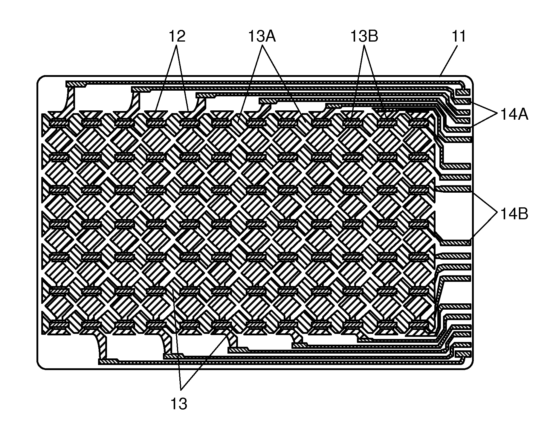
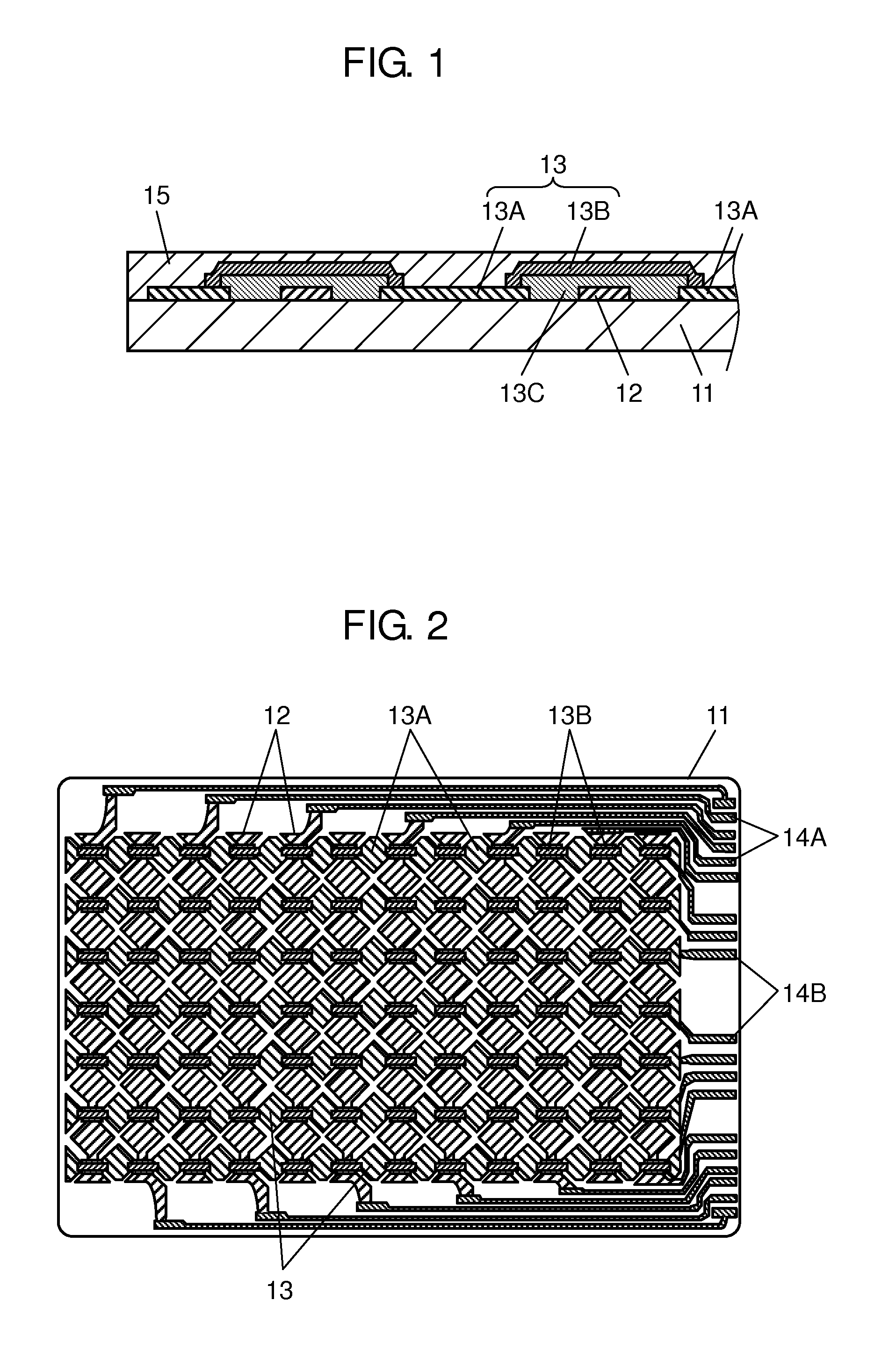
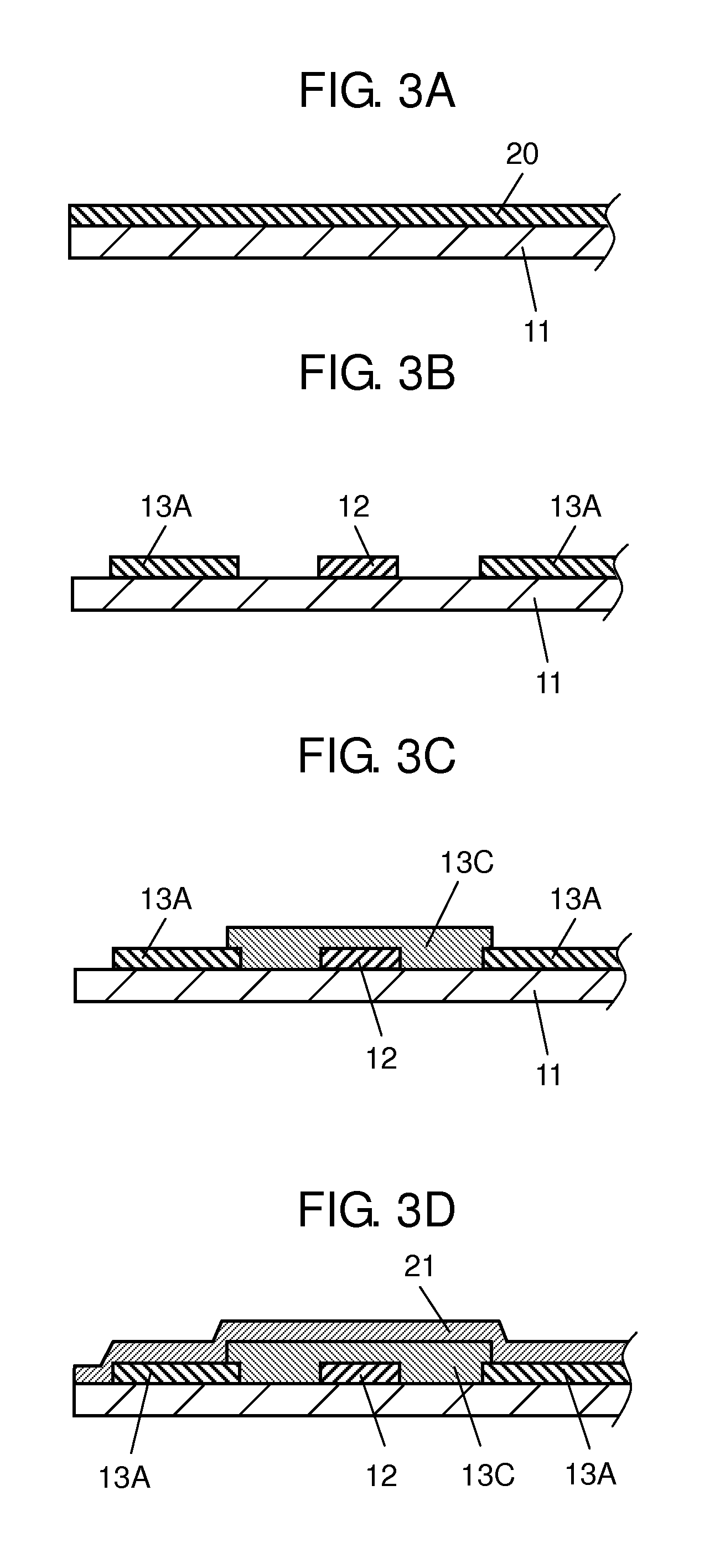
[0036]FIG. 1 is a cross-sectional view of a touch panel according to the present exemplary embodiment, and FIG. 2 is a plan view of the touch panel according to the present exemplary embodiment. Referring to FIGS. 1 and 2, reference numeral 11 represents a film-shaped light transmissive substrate made of material such as polyethylene terephthalate, polyether sulfone, or polycarbonate. A plurality of first conductive layers 12 are formed on an upper surface of substrate 11. First conductive layer 12 is made of light transmissive material such as indium tin oxide or tin oxide, and formed so as to extend in a roughly band-shaped form in a vertical direction. The vertical direction is assumed to be a first direction.

[0037]First conductive layer 12 is fo...


PUM

PropertyMeasurementUnit
diameteraaaaaaaaaa
diameteraaaaaaaaaa
transmittanceaaaaaaaaaa

Abstract

The touch panel includes a light transmissive substrate, a first light transmissive conductive layer, and a second light transmissive conductive layer. The first conductive layer is provided on an upper surface of the substrate, and extending in a roughly band-shaped form in a first direction. The second conductive layer is provided on the upper surface of the substrate, insulated from the first conductive layer, and extending in a roughly band-shaped form in a second direction perpendicular to the first direction. The first conductive layers and the second conductive layers are plurally provided. The second conductive layer includes conductive parts provided on the upper surface of the substrate, and a connecting part provided for connecting the conductive parts in the second direction, and provided above the first conductive layer, and material of the connecting part is resin containing dispersed conductive fine wires.

Description

BACKGROUND[0001]1. Technical Field[0002]The present invention relates to a touch panel mainly used for operating various kinds of electronic devices.[0003]2. Background Art[0004]Recently, as various kinds of electronic devices such as a cellular phone or a digital still camera have become highly functional and more diversified, an increasing number of electronic devices are mounting light transmissive touch panels on front surfaces of display elements such as a liquid crystal display element. Users can switch various functions of the electronic device by touching and operating the touch panel with a finger or the like while seeing a display of the display element provided on a back surface through the touch panel. The touch panel used as described above is required to be easy to recognize the display element on the back surface, low in cost, and capable of performing reliable operations.[0005]A conventional touch panel will be described with reference to FIG. 7.[0006]In FIG. 7, dime...

Claims


Application Information

Patent Timeline
Patent Type & Authority Applications(United States)
IPC IPC(8): H05K1/02
CPCH05K1/0274G06F3/0445G06F3/0446G06F2203/04103G06F2203/04111H05K1/0289H05K1/095H05K3/02H05K3/4685H05K2201/0108H05K2203/0514G06F3/041
Inventor TANABE, KOJIMURATA, KEISHIRO
Owner PANASONIC INTELLECTUAL PROPERTY MANAGEMENT CO LTD
Learn More