Apparatus, Pumping System Incorporating Same, and Methods of Protecting Pump Components

a technology applied in the field of apparatus and pumping system incorporating same, can solve the problems of submerged electric motors that are difficult to protect from corrosive agents and external fluids, and can be detrimental to the components of the submerged pumping system

Active Publication Date: 2007-04-05
SCHLUMBERGER TECH CORP
View PDF35 Cites 108 Cited by
  • Summary
  • Abstract
  • Description
  • Claims
  • Application Information

AI Technical Summary

Problems solved by technology

These corrosive agents can be detrimental to components of the submersible pumping system, particularly to internal electric motor components, such as copper windings and bronze bearings.
Moreover, irrespective of whether or not the fluid is corrosive, if the fluid enters the motor and mixes with the motor oil, the fluid can degrade the dielectric properties of the motor oil and the insulating materials of the motor components.
Submersible electric motors are difficult to protect from corrosive agents and external fluids because of their design requirements that allow use in the subterranean environment.
As the motor operates, however, heat is generated, which, in turn, heats the internal motor fluid causing expansion of the oil.
In many applications, submersible electric motors are subject to considerable temperature variations due to the subterranean environment, injected fluids, and other internal and external factors.
These temperature variations may cause undesirable fluid expansion and contraction and damage to the motor components.
For example, the high temperatures common to subterranean environments may cause the motor fluid to expand excessively and cause leakage and other mechanical damage to the motor components.
These high temperatures also may destroy or weaken the seals, insulating materials, and other components of the submersible pumping system.
Similarly, undesirable fluid expansion and motor damage can also result from the injection of high-temperature fluids, such as steam, into the submersible pumping system.
As a result, it becomes difficult to prevent the ingress of external fluids into the motor fluid and internal motor components.

Method used


Image

  • Apparatus, Pumping System Incorporating Same, and Methods of Protecting Pump Components
  • Apparatus, Pumping System Incorporating Same, and Methods of Protecting Pump Components
  • Apparatus, Pumping System Incorporating Same, and Methods of Protecting Pump Components

Examples


embodiment 50

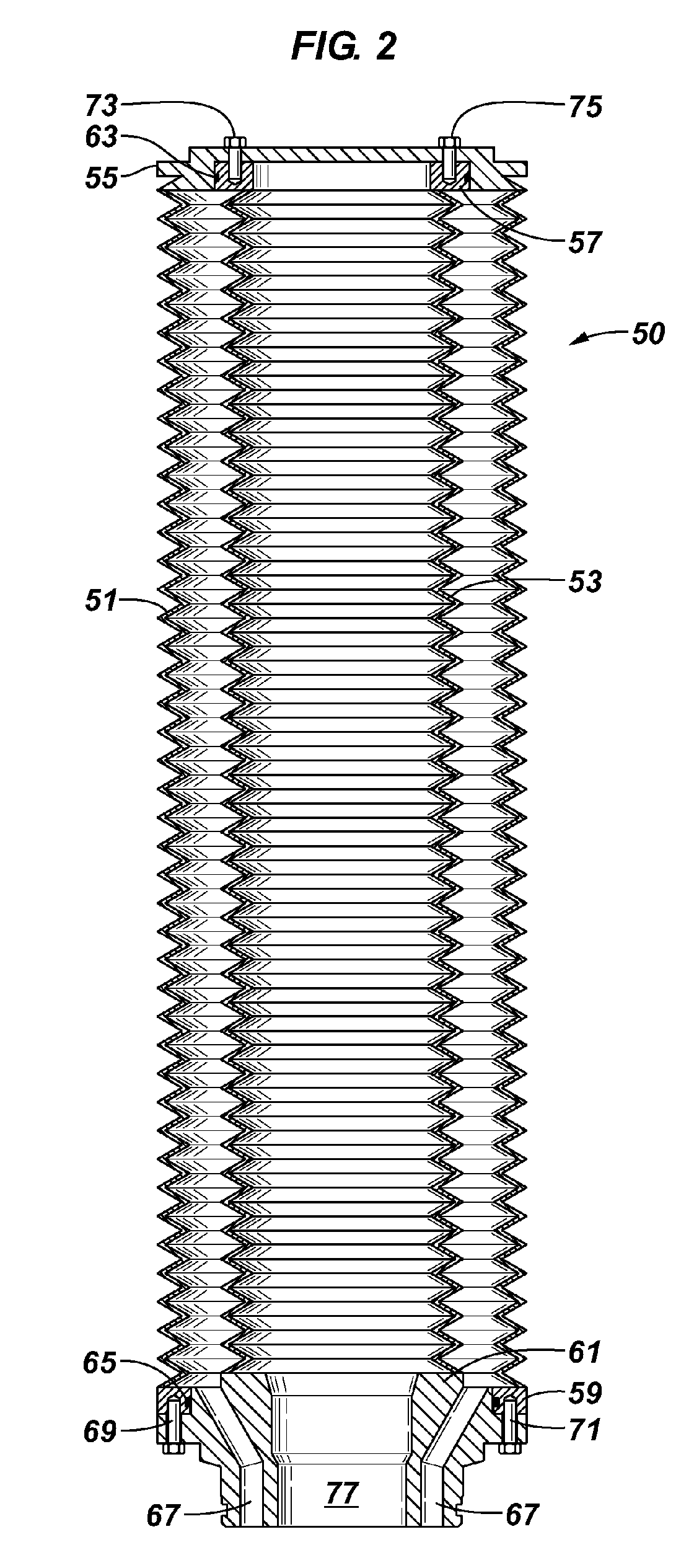
[0047] The present invention encompasses various ways using multi-piece bellows in a protector assembly. For example, the bellows can be designed into one, two, or more pieces depending on the actual cost and manufacturing capability. FIG. 2 illustrates in cross-section an embodiment 50 having a bellows that is in two pieces. One piece is an external bellows 51, and another piece is an internal bellows 53. Both bellows have upper and lower flanges so that the two bellows can be connected together to form an annular bellows. External bellows 51 is welded to an upper flange 55 and a lower flange 59, while internal bellows 53 is welded to an upper flange 57 and a lower flange 61. In some embodiments, like the embodiment illustrated in FIG. 2, o-rings 63 and 65 provide seals between each pair of the flanges to be connected together. Lower flange 61 of internal bellows 53 has one or more fluid communication ports 67, and flange 61 may serve as a male portion fitting into a female seat of...

embodiment 100

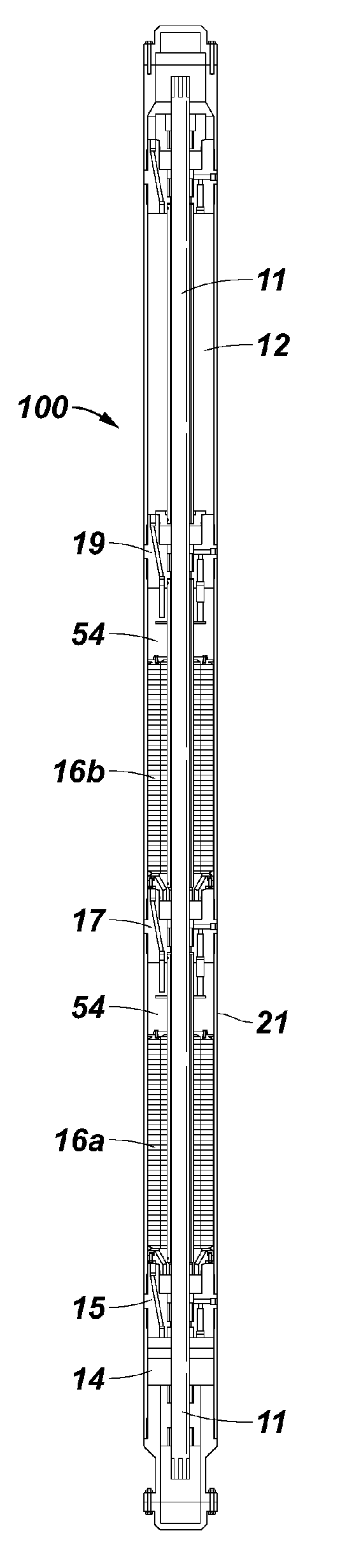
[0055] As discussed above, apparatus of the invention may have various configurations. For example, certain apparatus and systems of the invention may comprise a motor protector 16 that comprises a seal section 17 and a bellows section 51, 53 (FIG. 4). As illustrated in embodiment 100 of FIG. 3, seal section 17 may be disposed between pump 12 and motor 14, while a protector 16a is disposed adjacent motor 14, and another protector 16b is disposed on an opposite side of seal section 17. System 100 may also have an optional monitoring system disposed adjacent one of protectors 16a and / or 16b. If additional sealing and motor protection is desired, then a plurality of seal and bellows sections may be disposed about the motor 14 in desired locations. For example, certain systems of the invention may have multiple bellows sections disposed sequentially and / or on opposite sides of motor 14, such as a bellows section having two bellows assemblies in series.

[0056] Seal sections of a motor pro...


PUM


Abstract

Apparatus and pumping systems including the apparatus are described, the apparatus including a protector body comprising a material allowing expansion and contraction of an internal fluid, the body serving as a barrier between fluids external of the body and the internal fluid. The body has first and second ends, at least one end adapted to connect the body to other components, the protector body further comprising structural features permitting facile cleanout and reuse of the protector body. Methods of use of the apparatus and systems are described, particularly in oilfield exploration, testing, and production. This abstract allows a searcher or other reader to quickly ascertain the subject matter of the disclosure. It will not be used to interpret or limit the scope or meaning of the claims.

Description

CROSS-REFERENCE TO RELATED APPLICATIONS [0001] The present application claims priority under 35 U.S.C. § 119 to United States Provisional Application Ser. No. 60 / 596,523, filed Sep. 30, 2005, incorporated by reference herein in its entirety.BACKGROUND OF THE INVENTION [0002] 1. Field of Invention [0003] The present invention relates generally to the field of oilfield exploration, production, and testing, and more specifically to protection of pump components used in such ventures. [0004] 2, Related Art [0005] Electrical submersible pumps (ESPs) are used for artificial lifting of fluid from a well or reservoir. An ESP typically comprises an electrical submersible motor, a seal section (sometimes referred to in the art as a protector) which functions to equalize the pressure between the inside of the system and the outside of the system and also acts as a reservoir for compensating the internal oil expansion from the motor; and a pump having one or more pump stages inside a housing. T...

Claims


Application Information

Patent Timeline
Patent Type & Authority Applications(United States)
IPC IPC(8): E21B43/00
CPCE21B4/003E21B43/128
Inventor DU, MICHAEL H.ROWATT, JOHN D.DUVALL, CHERYL R.MILLER, MICHAEL W.
Owner SCHLUMBERGER TECH CORP
Why Eureka
Try Eureka