
Gift wrap dispensing system

a gift wrapping and dispensing system technology, applied in the field of gift wrapping, can solve the problems of inability to be stored in the most readily available household storage area, high risk of significant damage, and inconvenient to manufacture, etc., and achieve the effects of convenient storage and handling, compact size, and low cos

Inactive Publication Date: 2007-04-05
KING MEDORA
View PDF32 Cites 35 Cited by
  • Summary
  • Abstract
  • Description
  • Claims
  • Application Information

AI Technical Summary

Benefits of technology

[0014] It is another object of the present invention to provide a system of the type as described above which protects the gift wrap from potentially harmful conditions when stored away pending further use.
[0016] It is yet still another object of the present invention to provide a system as described above which has a limited number of parts, which is inexpensive to manufacture and which is easy to use.

Problems solved by technology

As a first drawback, it has been found that gift wrapping which is wound onto a length of rigid tubing lacks protection from many potentially harmful conditions, such as inadvertent contact, moisture and / or dust, thereby rendering the gift wrapping highly susceptible to significant damage, such as tearing, wrinkling and / or discoloration.
However, it is to be understood that such a container is typically constructed to be of a considerable size, thereby rendering it impossible of being stored within the most readily available household storage areas, such as cabinet drawers, shelves and closets, which is highly undesirable.
As a second drawback, it has been found that gift wrapping is typically packaged as rolls which are relatively large in size (approximately thirty-six inches in length), thereby rendering it somewhat difficult to handle during its use.
Furthermore, as noted above, a relatively large roll of gift wrapping is considerably difficult to store in the more conventional household storage areas, such as cabinet drawers, shelves and closets, which is highly undesirable.
As a third drawback, it has been found that the conventional means for packaging gift wrapping affords a user with no readily available instrument for separating a section of the gift wrapping from the remainder of the roll.
Rather, a separate cutting instrument, such as a pair of scissors, is typically required to separate a section of the gift wrapping from the remainder of the roll, thereby rendering the entire gift wrapping process more complicated in nature, which is highly undesirable.
Although well known in the art, commercial gift wrap dispensing systems of the type described above suffer from a couple notable drawbacks.
As a first drawback, commercial gift wrap dispensing systems of the type described above are traditionally designed to support rolls of gift wrapping which are at least 36 inches in length.
As a result, commercial gift wrap dispensing systems are similarly rather considerable in size.
Due to the substantial working and storage space required, such a system is typically limited to commercial applications and is not used in the more common residential (i.e., personal) applications, which is highly undesirable.
As a second drawback, commercial gift wrap dispensing systems of the type described above are not designed to protect the gift wrapping when stored away for future use.
In fact, when not in use, the gift wrapping remains exposed to potentially harmful conditions which can significantly damage the wrapping paper, which is highly undesirable.

Method used


Image

  • Gift wrap dispensing system
  • Gift wrap dispensing system
  • Gift wrap dispensing system

Examples


Embodiment Construction

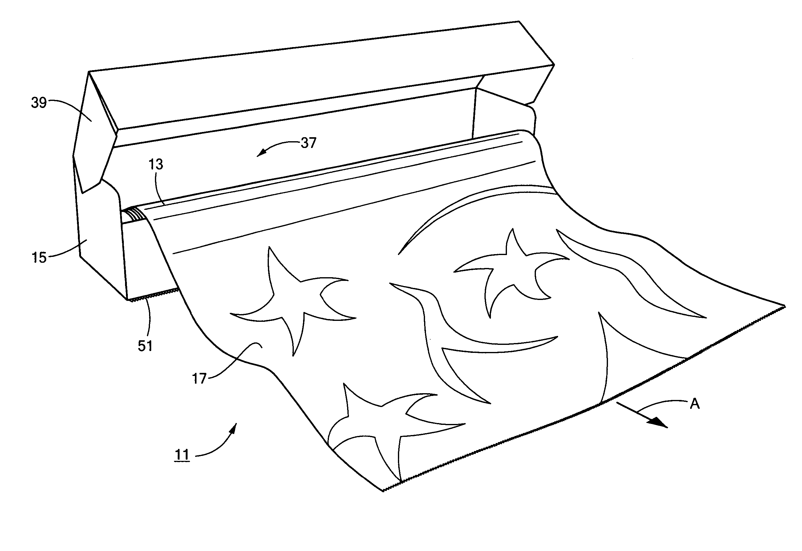
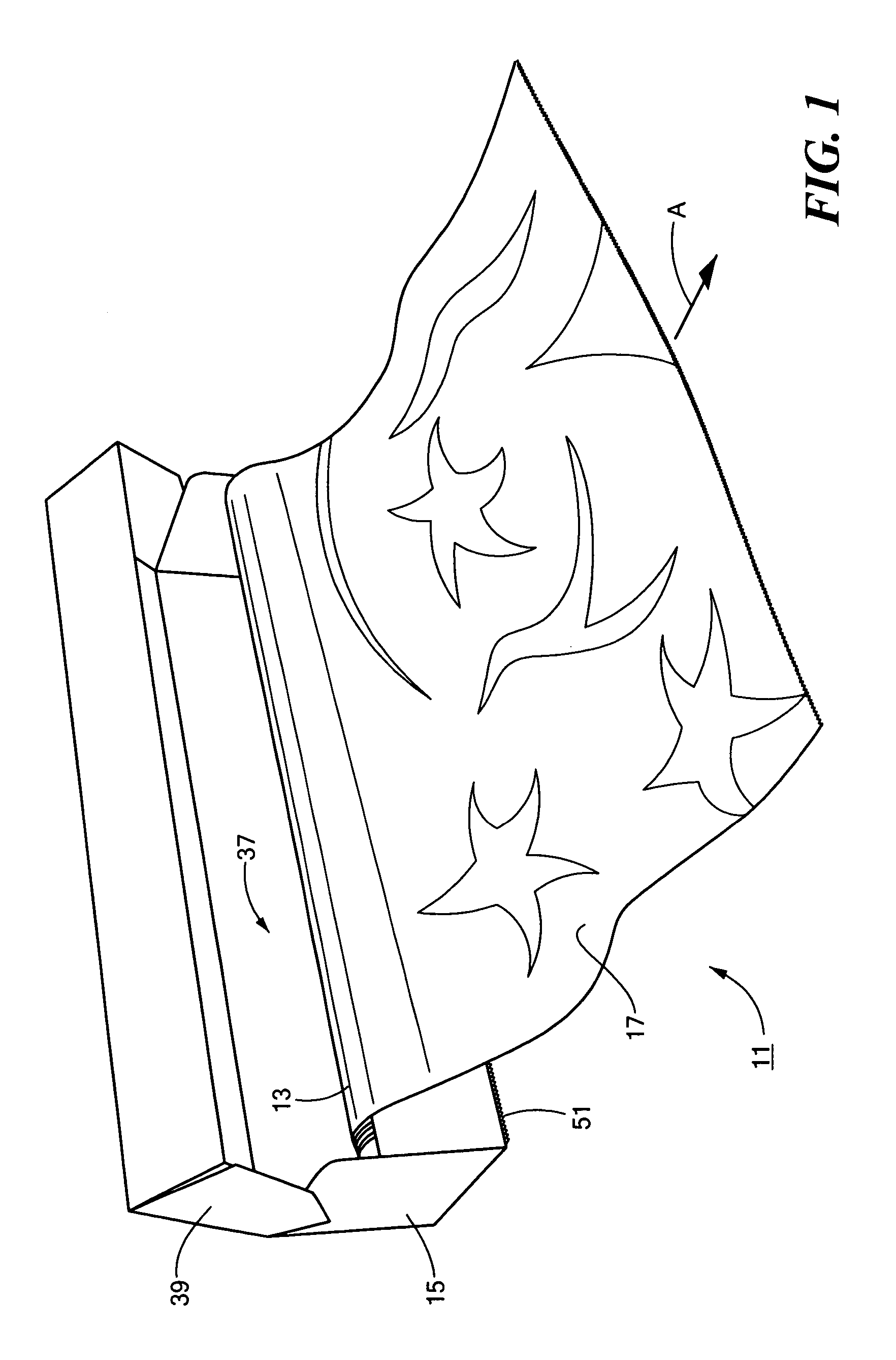
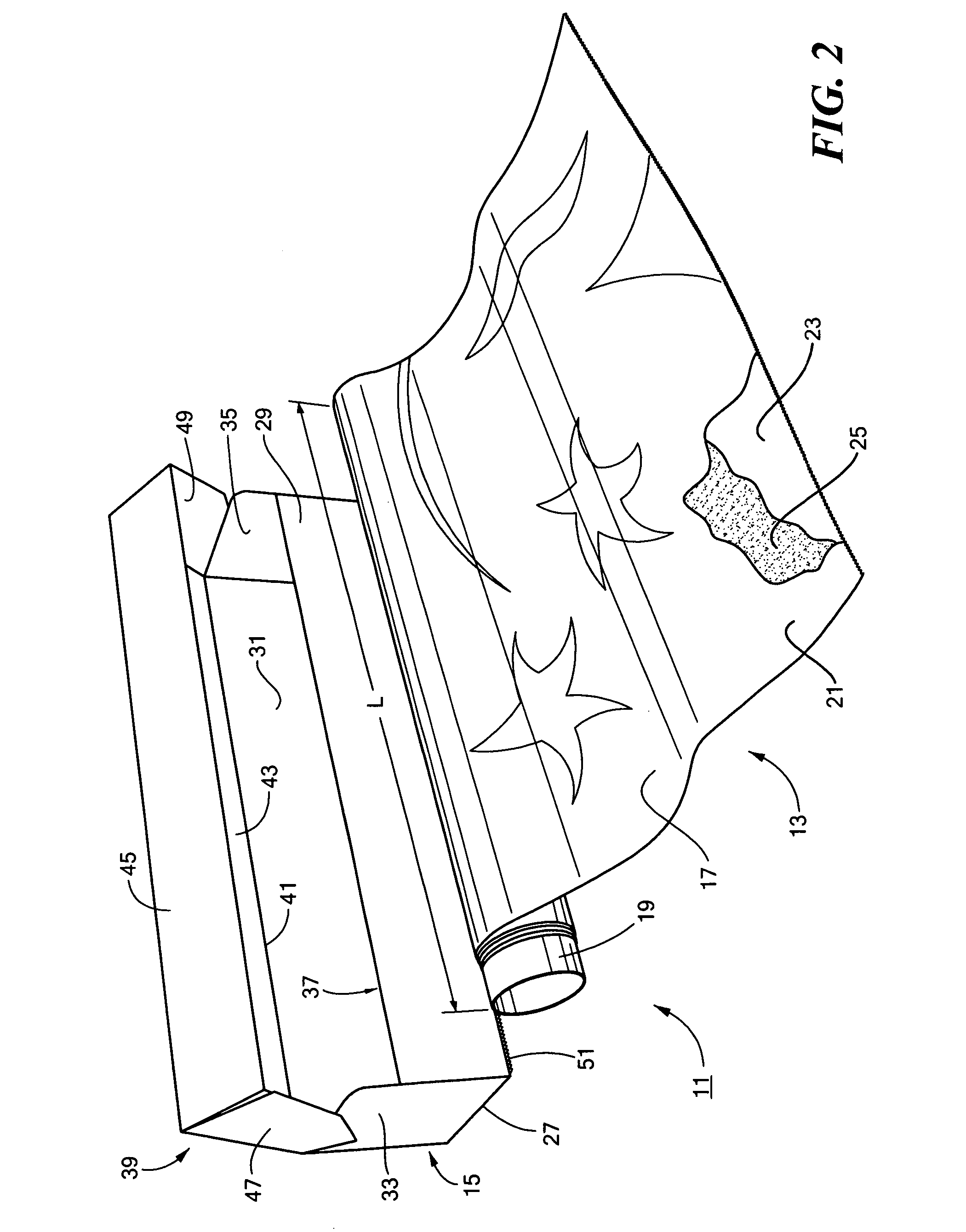
[0025] Referring now to FIGS. 1 and 2, there are shown perspective and exploded perspective views, respectively, of a novel system for dispensing gift wrap, the system being constructed according to the teachings of the present invention and identified generally by reference numeral 11.

[0026] Gift wrap dispensing system 11 comprises a roll of gift wrapping 13 that is retained within an enclosable carton 15.

[0027] As seen most clearly in FIG. 2, roll of gift wrapping 13 comprises a generally rectangular sheet of wrapping paper 17 that is wound onto a disposable tube 19. Tube 19 is preferably provided in the form of a hollow, cylindrical length of heavy paper or cardboard tubing which is suitably rigid so as to retain wrapping paper 17 in its rolled configuration.

[0028] It should be noted that the overall length L of roll of gift wrapping 13 is preferably in the range of approximately 10 inches to approximately 16 inches, which is considerably shorter in length than most convention...


PUM


Abstract

A gift wrap dispensing system includes a roll of gift wrapping that is retained within an enclosable carton. The roll of gift wrapping is in the range of approximately 10-16 inches in length and includes a rigid cardboard tube on which a supply of wrapping paper is wound. The wrapping paper includes a decorative film, such as a holographic or metallized film, that is bonded onto a coated paper substrate using a layer of bonding material. The carton is preferably constructed from a unitary cardboard blank and includes a bottom panel, a front panel, a rear panel and a pair of side panels which together define a longitudinal cavity which is sized and shaped to receive the roll of gift wrapping. The carton additionally includes a lid that is pivotally coupled to the rear panel and that is designed to be pivoted between an open position and a closed position. In order to dispense a supply of wrapping paper, the lid of the carton is pivoted at least partially open. A user-defined section of the wrapping paper is extracted from the carton and is severed from the remainder of the roll of gift wrapping using an externally-accessible serrated cutting edge that is mounted on the carton. With the section of wrapping paper dispensed, the lid is pivoted closed to protect the remainder of the roll of gift wrapping pending further use.

Description

BACKGROUND OF THE INVENTION [0001] The present invention relates generally to gift wrapping and more particularly to a novel system for dispensing gift wrapping. [0002] Gift wrapping (also commonly referred to in the art as gift wrap or wrapping paper) is well known in the art and is commonly used to cover presents for decorative purposes. Gift wrapping is most commonly used to wrap birthday and / or holiday gifts which are relatively compact in size and which are non-perishable in nature. [0003] Gift wrapping is typically manufactured in the form of an enlarged, rectangular, multi-layered sheet of highly decorative material that is customarily wound onto a disposable, hollow, cylindrical length of heavy paper or cardboard tubing. Commonly, rolls of gift wrapping are approximately thirty-six inches in length but may vary slightly in length to accommodate a variety of differently sized and shaped gifts. [0004] Gift wrapping is traditionally packaged for sale in its rolled form, with a ...

Claims


Application Information

Patent Timeline
IPC IPC(8): B65D85/00
CPCB65D83/0841
Inventor KING, MEDORA
Owner KING MEDORA
Learn More