Nose assembly for a fastener driving tool

a technology of driving tool and nose assembly, which is applied in the direction of nailing tools, packaging, paper/cardboard containers, etc., can solve the problems of nosepiece wear quickly, tool propulsion away from the fastener, and large stress on many parts of the tool, so as to reduce the weight of the tool and reduce the weight. , the effect of improving the durability of the nosepi

Inactive Publication Date: 2007-04-05
ILLINOIS TOOL WORKS INC
View PDF24 Cites 19 Cited by
  • Summary
  • Abstract
  • Description
  • Claims
  • Application Information

AI Technical Summary

Benefits of technology

[0008] The above-listed needs are met or exceeded by the present improved nosepiece for an internal combustion tool. First, the nose assembly includes a nosepiece having a first component that is integral with the sleeve and made of die cast aluminum for lower tool weight and heat dissipation, and a second component preferably made of steel for durability. The present nose assembly also includes a wear plate made of steel for protecting the aluminum portion. Also the present nose assembly allows for a reduction in weight, compared to conventional nose assemblies used in pneumatic tools. By using steel to construct the nosepiece's second component and the wear plate, the durability of the nosepiece has been increased. The steel wear plate protects the aluminum second component from excessive wear and weakening generated by the higher powered framing tools.

Problems solved by technology

In addition, the impact forces generated during fastener driving cause the tool to be propelled away from the fastener as it is driven into the substrate.
These forces put large stresses on many parts of the tool, especially causing the nosepiece to wear quickly.
Extended wear to the nosepiece may cause the sleeve to break or warp.
When either the nosepiece or the sleeve has to be replaced because they are bent or broken, a considerable amount of time and money is required to repair the tool.
This is because the nosepiece includes many parts and requires extensive and sometimes complicated disassembly.
As a result, higher power tools generate greater stresses that weaken conventional nosepieces, causing bending or even breaking of the sleeve or nosepiece or both.
Additionally, when the nosepiece bends or breaks, either the entire tool has to be discarded or the nosepiece or sleeve or both have to be replaced, which is expensive and time-consuming.
It is believed that, in addition to operator discomfort, the heat plays a factor in premature tool breakdowns.

Method used


Image

  • Nose assembly for a fastener driving tool
  • Nose assembly for a fastener driving tool
  • Nose assembly for a fastener driving tool

Examples


first embodiment

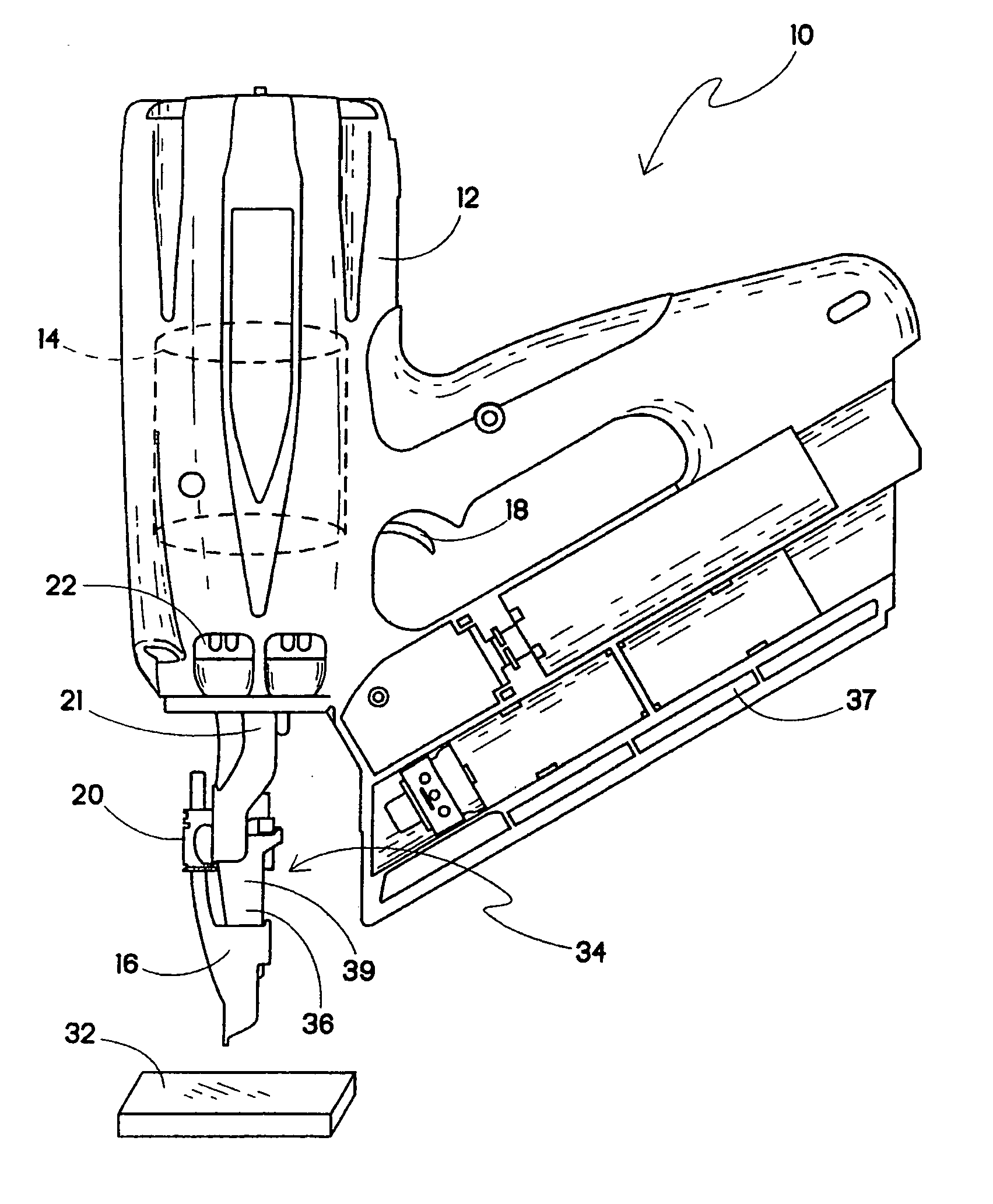
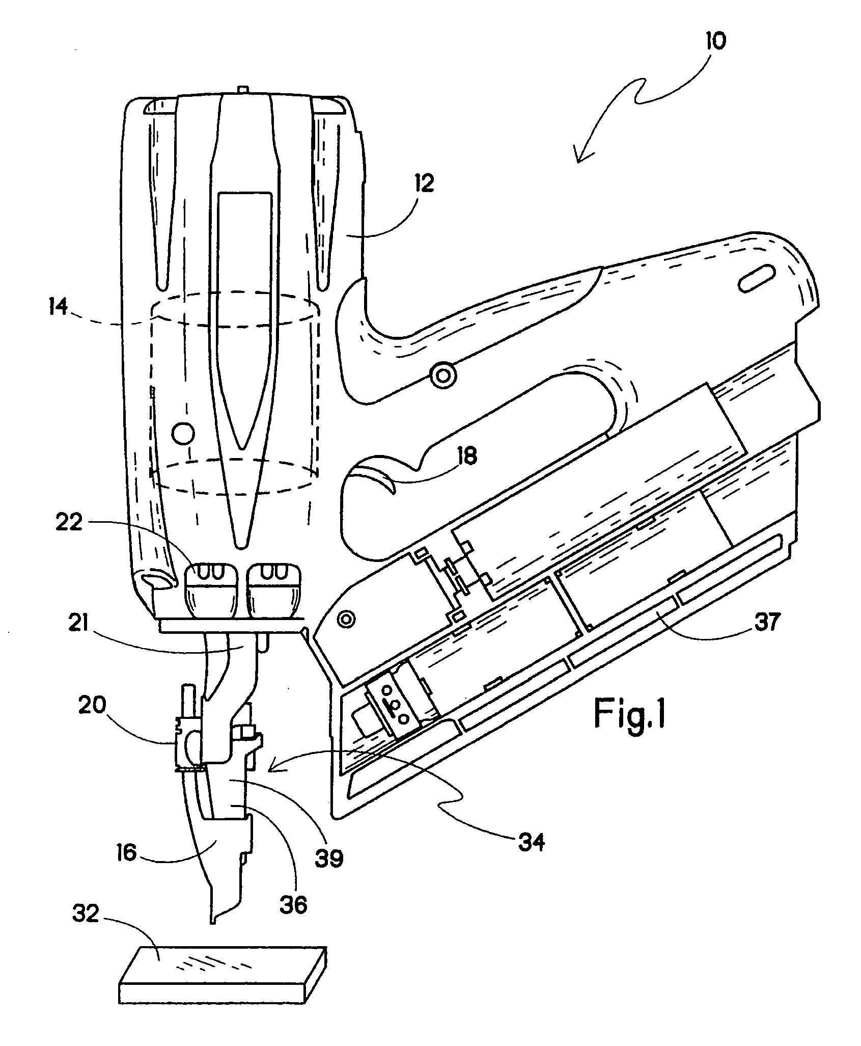
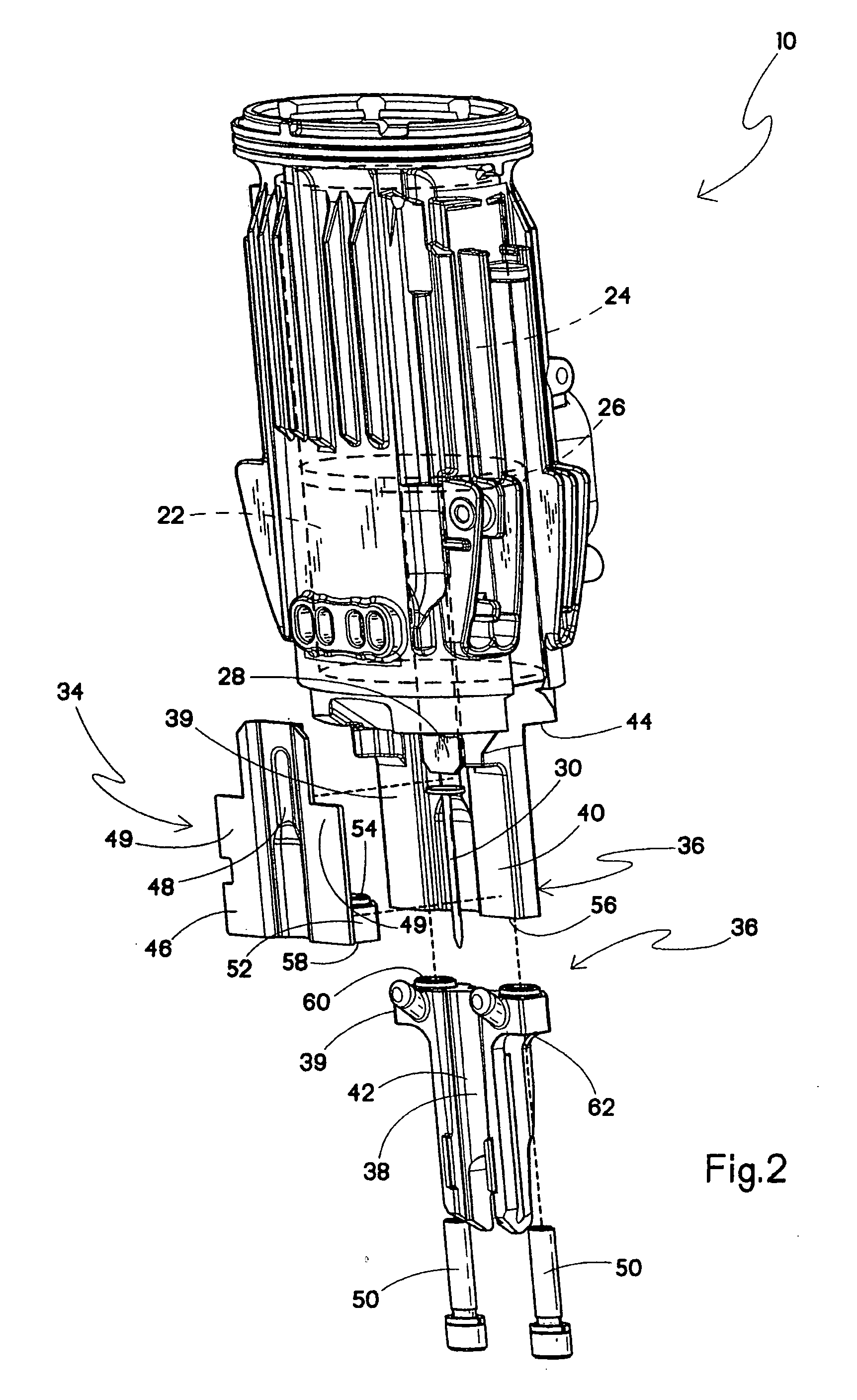
[0016]FIG. 2 depicts the present fastener driving tool 10 with a nose assembly 34 according to a Included in the nose assembly 34 is a nosepiece 36 that is associated with the sleeve 22. More specifically, the nosepiece 36 is constructed and arranged for receiving and guiding the driver blade 28 as it drives the fastener 30 into the substrate 32. Also, the nosepiece 36 receives fasteners 30 from a magazine 37 (FIG. 1). In most combustion powered tools, when both the workpiece contact element 16 and the trigger 18 are actuated, a gas / air mixture in the combustion chamber 14 is ignited. During combustion, the reciprocating piston 26 and driver blade 28 move axially within the sleeve 22 toward the substrate 32. As the driver blade 28 is forced out of the sleeve 22, it contacts the fastener 30 and drives the fastener along the nosepiece 36 and into the substrate 32. To facilitate this operation, the nosepiece 36 defines a channel 38 which receives and guides the driver blade 28 so that...

third embodiment

[0032] In the third embodiment, most of the differences between the nose assemblies 34 and 84 relate to the construction of a second component 86 and a wear plate 88, forming a nosepiece 90. As in the case of the nose assembly 34, the fasteners 50 extend along the longitudinal axis of the nose assembly 84. As seen in FIG. 4, the second component 86 and the wear plate 88 are integral with each other and form one unitary structure 92 which protects the first component 40 and the sleeve 22 from excessive wear. In addition, as in the nose assembly 34, the first component 40 is preferably integral with the aluminum sleeve 22. This configuration allows for easy installation or removal of the nose assembly 84. More specifically, the unitary structure 92 formed by the second component 86 and the wear plate 88 may be removed or installed easily by removing the at least one assembly fastener 50.


PUM


Abstract

A fastener driving tool includes a sleeve defining a cylinder for accommodating a reciprocating piston and a driver blade for driving a fastener into a substrate. In addition, the tool includes a nose assembly having a nosepiece associated with the sleeve and is constructed and arranged for receiving and guiding the driver blade as it drives the fastener into the substrate. The nosepiece has a body including a first component made of one material and a second component made of a second material.

Description

BACKGROUND [0001] The present invention relates to an improved nose assembly for fastener driving tools, particularly those used for framing. More specifically, the present invention relates to improvements of the nosepieces for such tools. [0002] While such tools are typically powered by pneumatic, combustion, electric, or powder systems, and the present nose assembly is contemplated as usable on fastener driving tools regardless of the power system, the main focus will be on combustion tools. Portable combustion powered fastener driving tools, such as those manufactured by ITW Paslode under the IMPULSE® brand, have been typically manufactured to operate with an integrated aluminum die cast sleeve having an attached nosepiece. Such tools incorporate a tool housing enclosing a small internal combustion engine. The engine is powered by a canister of pressurized fuel gas called a fuel cell. A battery-powered electronic power control unit produces the spark for ignition, and a fan loca...

Claims


Application Information

Patent Timeline
Patent Type & Authority Applications(United States)
IPC IPC(8): B25C3/00
CPCB25C1/008B25C1/08
Inventor PORTH, CHRIS H.SHKOLNIKOV, YURYVAHABI-NEJAD, MARIAMWALTHALL, BARRY C.
Owner ILLINOIS TOOL WORKS INC
Why Eureka
Try Eureka