Interlaced linear array sampling technique for electromagnetic wave imaging

a linear array and electromagnetic wave technology, applied in the field of microwave and millimeter wave holographic imaging techniques, can solve the problems of antenna coupling problems, the array of antennas is the major cost of these systems, and the microwave/millimeter wave transceiver must be capable, etc., to achieve the effect of equal resolution

Active Publication Date: 2007-04-05
BATTELLE MEMORIAL INST
View PDF13 Cites 42 Cited by
  • Summary
  • Abstract
  • Description
  • Claims
  • Application Information

AI Technical Summary

Benefits of technology

[0024] As will be shown in the detailed description of the present invention set forth below, numerous configurations of receivers and transmitters fulfilling the requirement that at least one transmitter is configured to transmit a signal to three or more receivers and at least one receiver is configured to receive a signal from three or more tra

Problems solved by technology

In these and other configurations, a major cost of these systems is the array of antennas.
This forces the antenna to be very small, and therefore low-gain, and will frequently cause antenna coupling problems between adjacent or neighboring antennas.
An additional problem is that the microwave/m

Method used


Image

  • Interlaced linear array sampling technique for electromagnetic wave imaging
  • Interlaced linear array sampling technique for electromagnetic wave imaging
  • Interlaced linear array sampling technique for electromagnetic wave imaging

Examples


Embodiment Construction

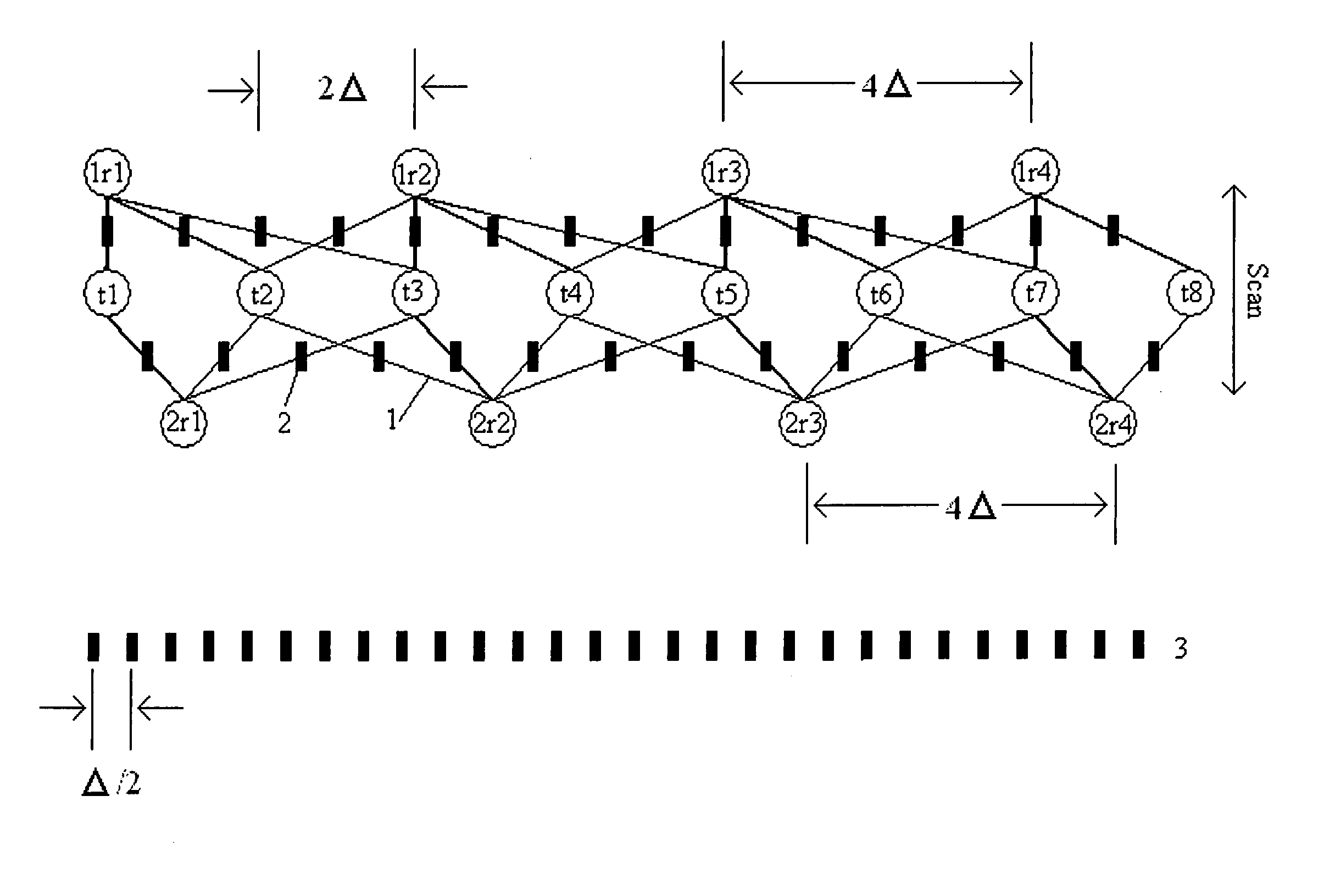
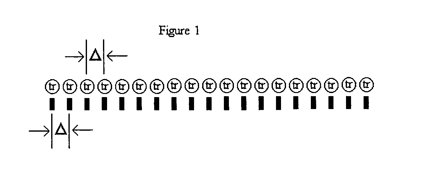
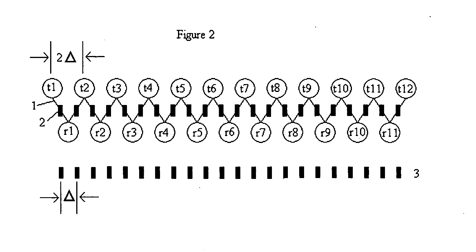
[0031] For the purposes of promoting an understanding of the principles of the invention, FIGS. 2 through 5 show various configurations of sampling systems utilizing linear arrays. As will be recognized by those having ordinary skill in the art, the figures show what would typically only be a portion of the arrays used in actual systems, as in many applications the size of the object imaged by these systems necessitates much longer arrays. Accordingly, the examples shown in FIGS. 2 through 5 are only intended to be illustrative of the general principles with respect to how various elements within the arrays may be used to achieve the advantages of the present invention, and the invention should in no way be limited to either the number of elements shown in these illustrative examples, or the arrangement of these elements within these illustrative examples.

[0032] For example, and not meant to be limiting, those having ordinary skill in the art and the benefit of this disclosure will...


PUM


Abstract

An arrangement of receivers and transmitters used in wideband holographic imaging using a reduced number of physical antenna elements compared to established techniques and systems. At least one of the receivers is configured to receive the reflected signal from three or more of transmitters, and at least one transmitter is configured to transmit a signal to an object, the reflection of which will be received by at least three receivers. The improved arrays are easily incorporated into existing microwave and millimeter wave holographic imaging equipment utilizing the existing mechanical features of this equipment, as well as the existing wideband holographic imaging algorithms and electronics for constructing images.

Description

[0001] This invention was made with Government support under Contract DE-AC0576RLO 1830, awarded by the U.S. Department of Energy. The Government has certain rights in the invention.TECHNICAL FIELD [0002] This invention relates to microwave and millimeter wave holographic imaging techniques. Specifically, this invention relates to a method and apparatus that allows millimeter wave holographic imaging equipment to operate with fewer antennas, thereby greatly reducing the cost of these systems with no degradation in system performance. BACKGROUND OF THE INVENTION [0003] Over the past ten years, the inventors of the present invention have been active in researching, fabricating, and demonstrating millimeter wave holographic imaging techniques. In the course of this effort, they and others have published numerous patents and other publications that describe millimeter wave holographic imaging techniques generally, as well as specific improvements and enhancements. A review of this liter...

Claims


Application Information

Patent Timeline
IPC IPC(8): G01S13/89
CPCG01S13/89H01Q21/22G01B9/02047H01Q3/24
Inventor SHEEN, DAVIDMCMAKIN, DOUGLAS
Owner BATTELLE MEMORIAL INST
Why Eureka
Try Eureka