Apparatus and method for measuring color

a technology of objects and apparatus, applied in the field of devices and methods for measuring the color of objects, can solve the problems of limiting the practical application of such instruments, limiting the applicability of such a method, and difficulties with conventional techniques

Inactive Publication Date: 2007-04-05
RPX CORP +1
View PDF83 Cites 1 Cited by
  • Summary
  • Abstract
  • Description
  • Claims
  • Application Information

AI Technical Summary

Benefits of technology

[0016] In accordance with the present invention, devices and methods are provided for measuring the color of objects, reliably and with minimal problems of height and angular dependence. A handheld probe is utilized in the present invention, with the handheld probe containing a number of fiber optics. Light is directed from one (or more) light source fiber optics towards the object to be measured, which in certain preferred embodiments is a central light source fiber optic (other light source arrangements also may be utilized). Light reflected from the object is detected by a number of light receiver fiber optics. Included in the light receiver fiber optics are a plurality of perimeter fiber optics. In certain preferred embodiments, three perimeter fiber optics are utilized in order to take measurements at a desired, and predetermined height and angle, thereby minimizing height and angular dependency problems found in conventional methods. In certain embodiments, the present invention also may measure translucence and fluorescence characteristics of the object being measured, as well as surface texture and / or other surface characteristics.

Problems solved by technology

Such instruments typically require a broad band spectrophotometer, which generally are expensive, bulky and relatively cumbersome to operate, thereby limiting the practical application of such instruments.
There are, however, difficulties with the conventional techniques.
The fixed mounting arrangement greatly limits the applicability of such a method.
Such an apparatus tends to be very difficult to utilize on small objects or on objects that are hard to reach, and in general does not work satisfactorily in measuring objects with curved surfaces.
Unfortunately, however, the best match often is affected by the ambient light color in the dental operatory and the surrounding color of the patient's makeup or clothing and by the fatigue level of the dentist.
There are numerous paint guides available in the industry and the color determination also often is affected by ambient light color, user fatigue and the color sensitivity of the user.
Many individuals are color insensitive (color blind) to certain colors, further complicating color determination.
With respect to such applications, however, the limitations of conventional color measuring techniques typically restrict the utility of such techniques.
For example, the high cost and bulkiness of typical broad band spectrometers, and the fixed mounting arrangements or feet required to address the height and angular dependency, often limit the applicability of such conventional techniques.
Moreover, another limitation of such conventional methods and devices are that the resolution of the height and angular dependency problems typically require contact with the object being measured.
In certain applications, for example, hygienic considerations make such contact undesirable.
In the other applications such as interior decorating, contact with the object can mar the surface (such as if the object is coated with wet paint) or otherwise cause undesirable effects.

Method used


Image

  • Apparatus and method for measuring color
  • Apparatus and method for measuring color
  • Apparatus and method for measuring color

Examples


Embodiment Construction

[0043] The present invention will be described in greater detail with reference to certain preferred embodiments.

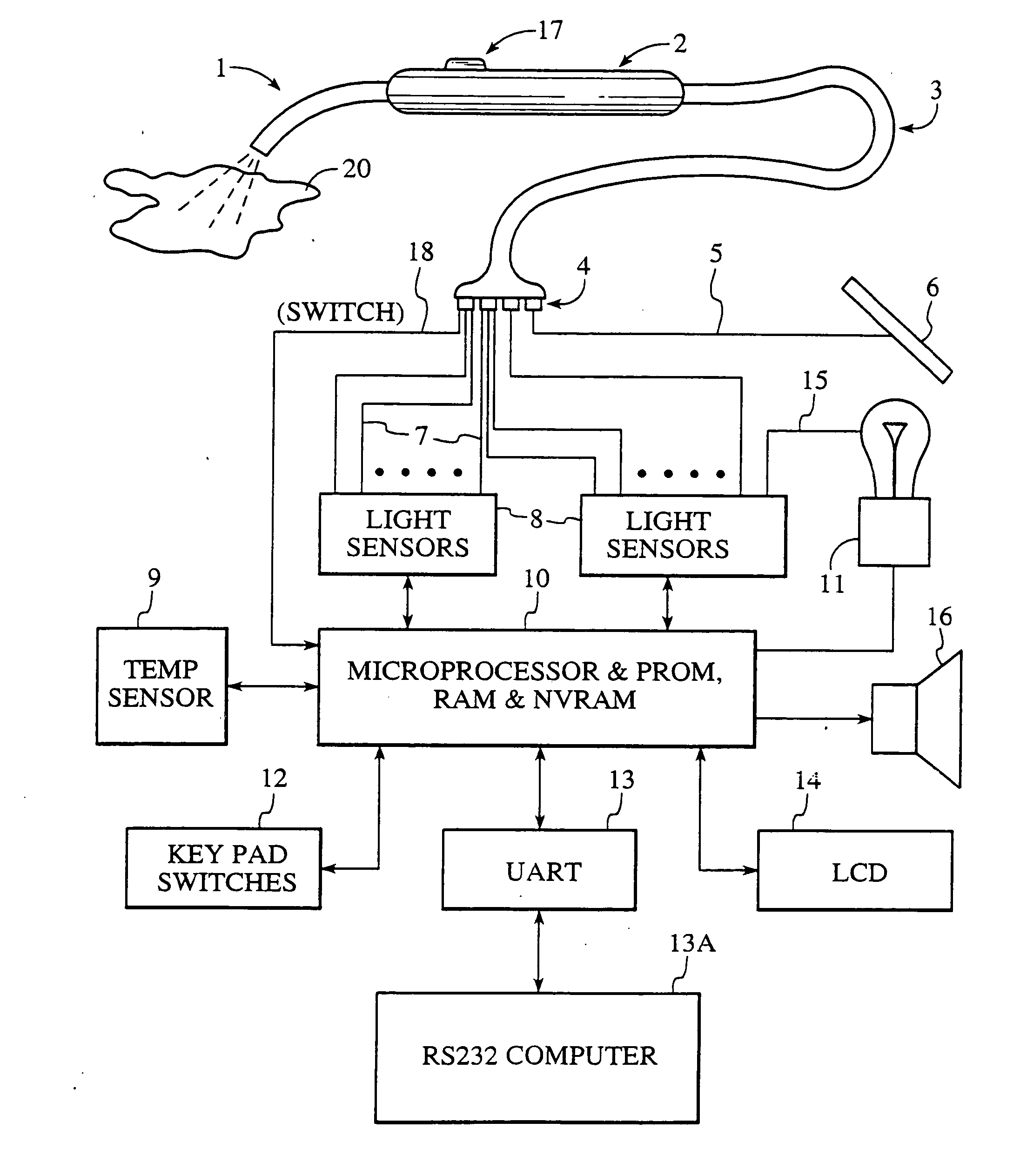
[0044] With reference to FIG. 1, an exemplary preferred embodiment of a color measuring system and method in accordance with the present invention will be described.

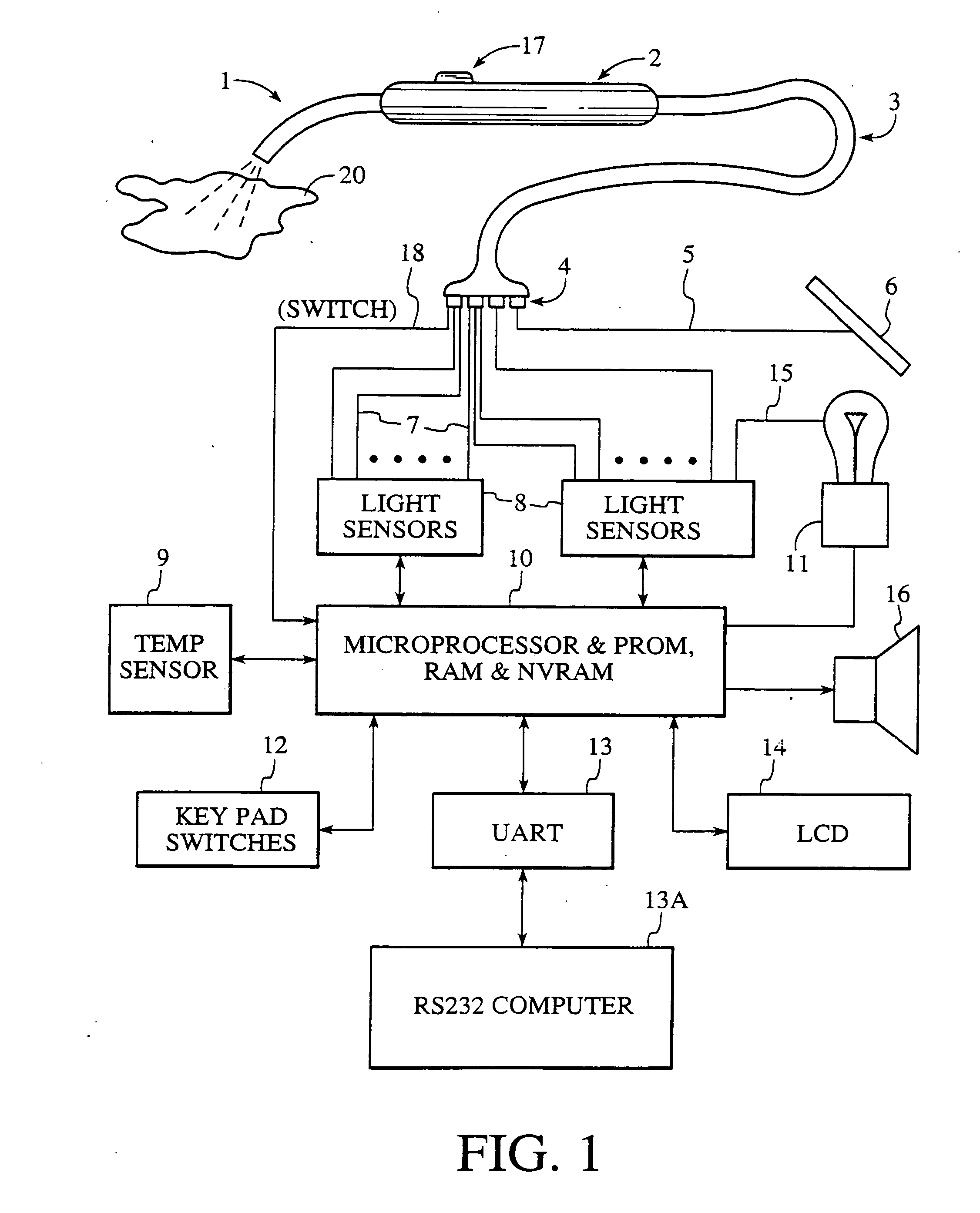
[0045] Probe tip 1 encloses a plurality of fiber optics, each of which may constitute one or more fiber optic fibers. In a preferred embodiment, the fiber optics contained within probe tip 1 includes a single light source fiber optic and three light receiver fiber optics. The use of such fiber optics to measure the color of an object will be described later herein. Probe tip 1 is attached to probe body 2, on which is fixed switch 17. Switch 17 communicates with microprocessor 10 through wire 18 and provides, for example, a mechanism by which an operator may activate the device in order to make a color measurement. Fiber optics within probe tip 1 terminate at the forward end thereof (i.e., the end away from p...


PUM

PropertyMeasurementUnit
angleaaaaaaaaaa
critical angleaaaaaaaaaa
color measurementaaaaaaaaaa

Abstract

Color measuring systems and methods are disclosed. Perimeter receiver fiber optics are spaced apart from a central source fiber optic and receive light reflected from the surface of the object being measured. Light from the perimeter fiber optics pass to a variety of filters. The system utilizes the perimeter receiver fiber optics to determine information regarding the height and angle of the probe with respect to the object being measured. Under processor control, the color measurement may be made at a predetermined height and angle. Various color spectral photometer arrangements are disclosed. Translucency, fluorescence and / or surface texture data also may be obtained. Audio feedback may be provided to guide operator use of the system. The probe may have a removable or shielded tip for contamination prevention.

Description

FIELD OF THE INVENTION [0001] The present invention relates to devices and methods for measuring the color of objects, and more particularly to devices and methods for measuring the color of teeth, fabric or other objects or surfaces with a hand-held probe that presents minimal problems with height or angular dependencies. BACKGROUND OF THE INVENTION [0002] Various color measuring devices such as spectrophotometers and colorimeters are known in the art. To understand the limitations of such conventional devices, it is helpful to understand certain principles relating to color. Without being bound by theory, Applicants provide the following discussion. [0003] The color of an object determines the manner in which light is reflected from the surface of the object. When light is incident upon an object, the reflected light will vary in intensity and wavelength dependent upon the color of the surface of the object. Thus, a red object will reflect red light with a greater intensity than a...

Claims


Application Information

Patent Timeline
Patent Type & Authority Applications(United States)
IPC IPC(8): G01N21/25G01J3/51A61B1/00A61B1/24A61C19/10G01J3/02G01J3/04G01J3/10G01J3/46G01J3/50G01N21/47G01N21/57
CPCA61B2560/0233A61C19/10G01J3/02G01J3/0218G01J3/0264G01J3/0272G01J3/0291G01J3/0297G01J3/04G01J3/10G01J3/46G01J3/50G01J3/508G01J3/51G01J3/513G01J3/524G01N21/251G01N21/474G01N21/57G01N2021/6484A61B2560/0223G01J3/0208
Inventor JUNG, WAYNE D.JUNG, RUSSELL W.LOUDERMILK, ALAN R.
Owner RPX CORP
Why Eureka
Try Eureka