

Ophthalmic microscope
a microscope and ophthalmology technology, applied in the field of ophthalmology microscopes, can solve the problems of reduced visibility, unfavorable fusion of images, reduced visual performance, etc., and achieve the effects of reducing price, widening the observation range of the inspecting eye, and changing quickly
- Summary
- Abstract
- Description
- Claims
- Application Information
AI Technical Summary
Benefits of technology
Problems solved by technology
Method used
Image

Examples
embodiment 1
[Embodiment 1]
(Structure of each Component and the Entirety of the Ophthalmic Microscope)
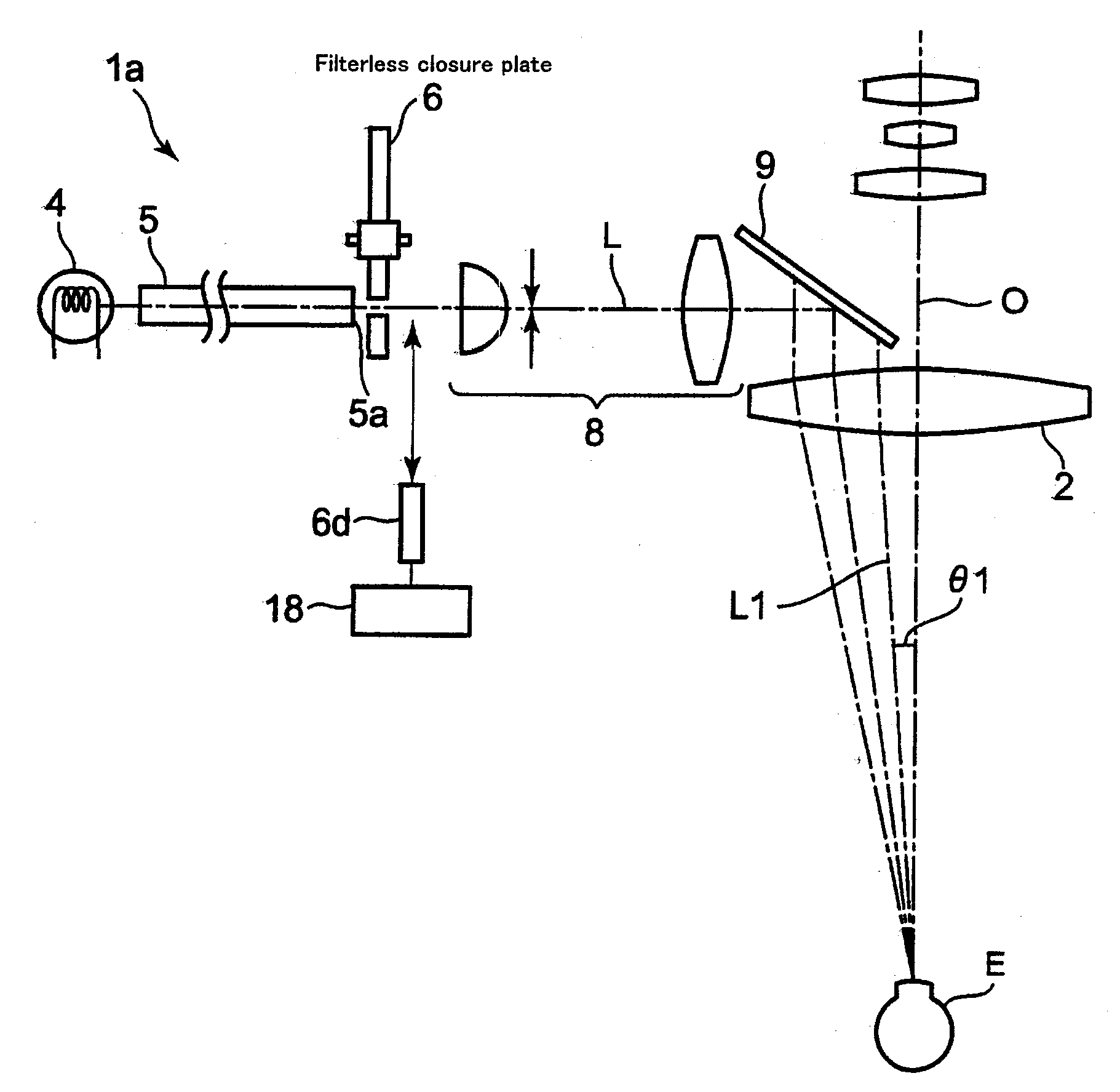
[0033] Embodiment 1 of the present invention is an ophthalmic microscope equipped with a filter, which is a component of the correlated color temperature changing means, for changing the correlated color temperature, wherein the correlated color temperature changing means and the lighting angle switching means are constituted together by employing a closure plate containing a transparent piece that is a component of the lighting angle switching means.
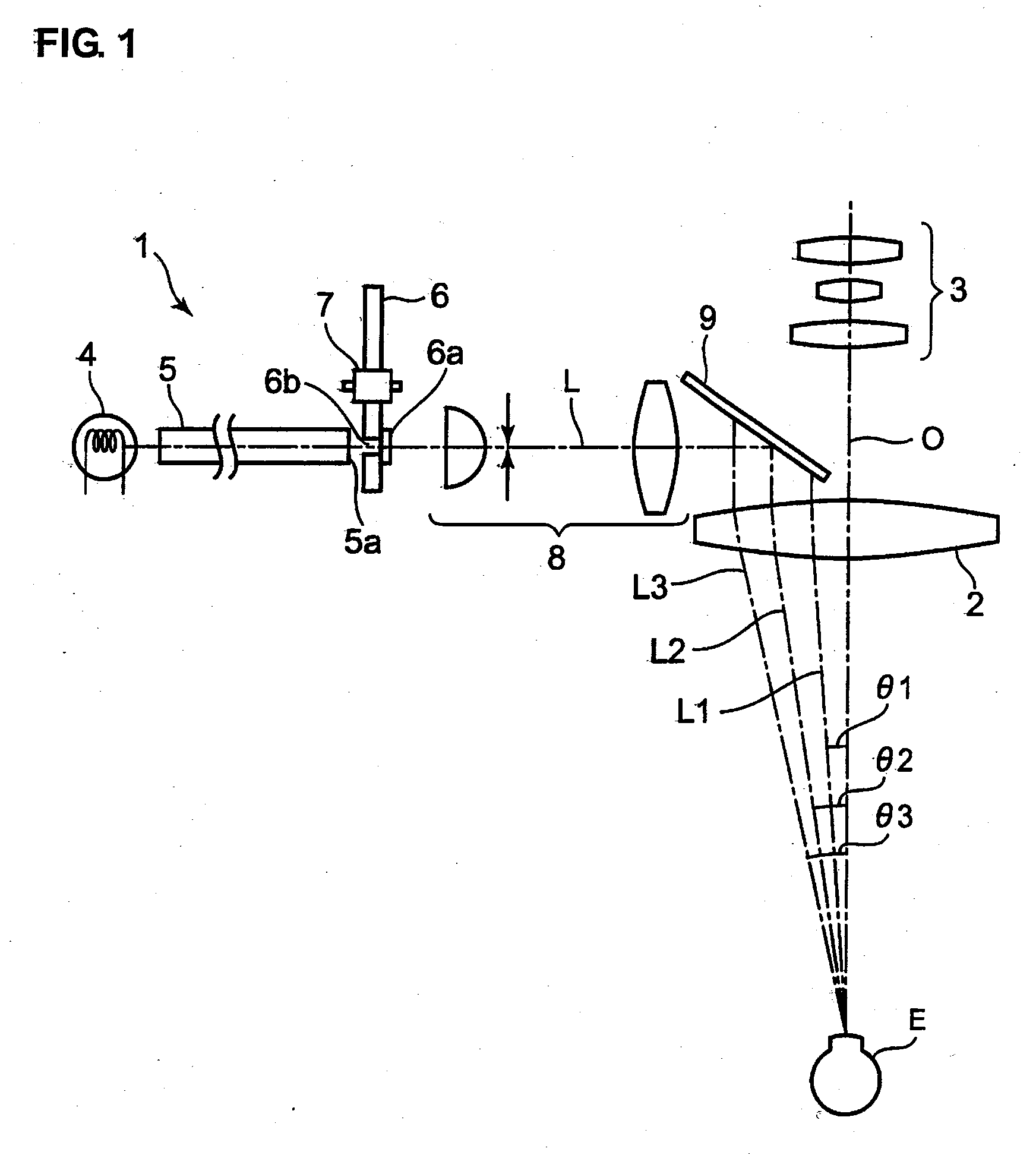
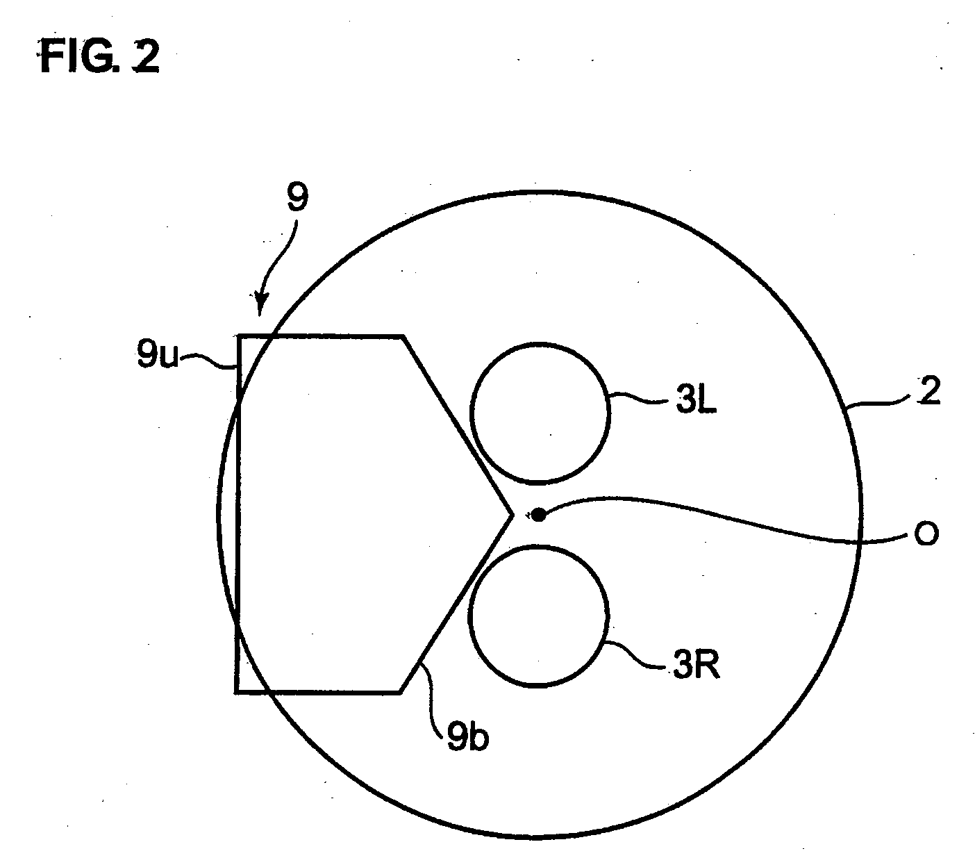
[0034]FIG. 1 shows an outlined structure of the ophthalmic microscope 1 in the embodiment of the present invention. The ophthalmic microscope 1 enables observation through binocular vision. For example, it is placed on the objective lens 2 opposite to the inspecting eye E and the extension of the optical axis of the objective lens 2. The ophthalmic microscope 1 is equipped with an ocular lens component comprising an ocular lens for the left and r...
embodiment 2
[Embodiment 2]
[0056] In Embodiment 1, an ophthalmic microscope equipped with a halogen light source was explained for the purpose of example. It is also possible to place a xenon light source in the ophthalmic microscope of said Embodiment 1 and Embodiments 3 and 4 mentioned below. Furthermore, since the components are almost the same except for the xenon light source and the closure plate 61 shown in FIG. 7, only different components will be explained to clarify the difference from Embodiment 1.
[0057] When using the ophthalmic microscope equipped with a xenon light source, the correlated color temperature changing filter is used to change the correlated color temperature of the illumination light from 6000K to 3000K. The closure plate 61 formed in a disc shape, as shown in FIG. 7 for example, is used as the correlated color temperature changing means. Similar to the closure plate 6 (see FIG. 3A), the transparent pieces 61b1 to 61b4 are open near the periphery of the closure plate ...
embodiment 3
[Embodiment 3]
(Structure of Each Part and the Entire Ophthalmic Microscope)
[0060] Embodiment 3 of the present invention is an ophthalmic microscope comprising a closure plate containing a correlated color temperature changing filter which is a component of the correlated color temperature changing means, and a transparent piece which is a component of the lighting angle switching means, different from the constitution of the microscope of Embodiment 1, wherein the color temperature changing means and the lighting angle switching means are separately constituted.
[0061] The difference from the ophthalmic microscope of Embodiment 1 is that the ophthalmic microscope comprises said closure plate 6 and said correlated color temperature changing filter 6a shown in FIG. 3A as individual components, wherein said closure plate 6 works in conjunction with the correlated color temperature changing filter 6a to drive. The closure plate 6 used in the explanation, i.e. the closure plate 6 on wh...
PUM
 Abstract
Description
Claims
Application Information