Micro camera module with discrete manual focal positions

a micro camera and manual focal position technology, applied in the field of cameras, can solve the problems of increasing the number of parts and assembly time, shortening the battery life, and contributing to the overall cost of the camera

Inactive Publication Date: 2007-04-05
NANCHANG O FILM OPTICAL ELECTRONICS TECH CO LTD
View PDF4 Cites 82 Cited by
  • Summary
  • Abstract
  • Description
  • Claims
  • Application Information

AI Technical Summary

Benefits of technology

[0014] The housing is mounted to a substrate over an image capture device also mounted on the substrate. The example housing shown is mounted via a plurality of posts extending from the bottom of the base of the housing. The posts are fixed within apertures formed in the substrate for that ...

Problems solved by technology

While continuously adjustable lens mechanisms facilitate precise focus at virtually any focal distance in the range, their complexity introduces a variety of disadvantages.
One disadvantage is that electrical drive units require power, which shortens battery life.
Another disadvantage is the increased number of parts and required assembly time, both of which contribute to the overall cost of the camera.
The complexity also increases possible sources of failure and, therefore, results in a decreased reliability for the camera.
Yet another disadvantage is that the complexity of the device increases the overall size of the camera.
Despite the advantages provided by the multiple discrete position, manually operated focus mechanism, this type of mechanism has not been successfully implemented in miniature camera modules, such as camera modules now incorporated into c...

Method used


Image

  • Micro camera module with discrete manual focal positions
  • Micro camera module with discrete manual focal positions
  • Micro camera module with discrete manual focal positions

Examples


Embodiment Construction

[0031] The present invention overcomes the problems associated with the prior art, by providing a micro camera module with a plurality of discrete manual focal positions. In the following description, numerous specific details are set forth (e.g., particular lens assemblies, particular construction materials, etc.,) in order to provide a thorough understanding of the invention. Those skilled in the art will recognize, however, that the invention may be practiced apart from these specific details. In other instances, details of well known electronic manufacturing and assembly practices and components have been omitted, so as not to unnecessarily obscure the present invention.

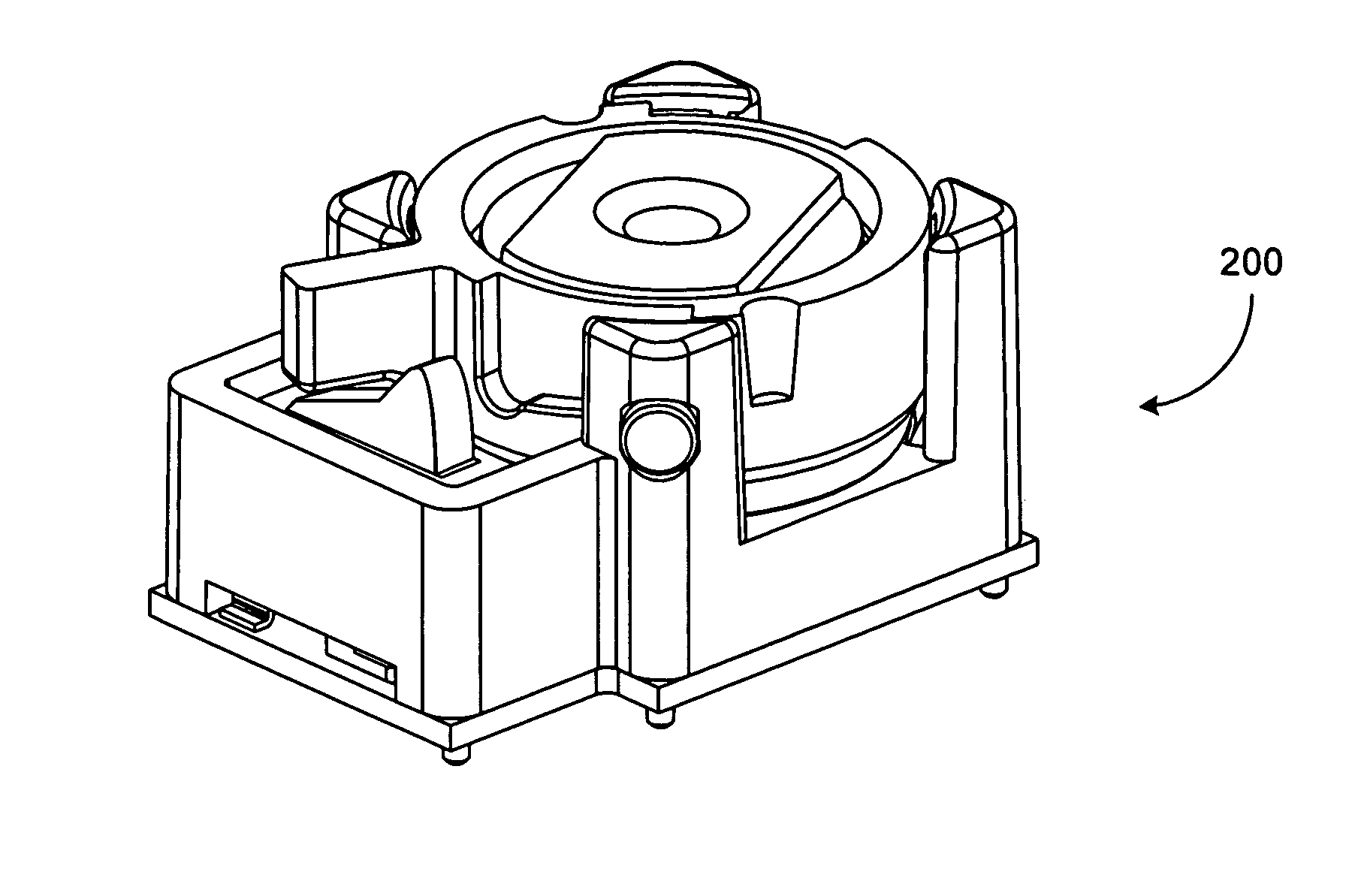
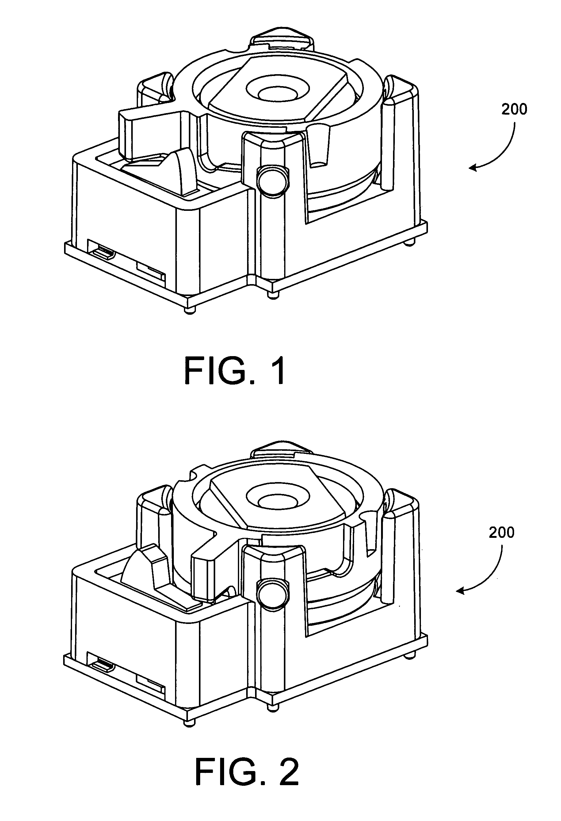
[0032]FIGS. 1 and 2 show an assembled camera module 200 in first and second discrete focal positions, respectively. In this particular embodiment, camera module 200 includes a close focal position and an infinite focal position. In the first focal position, camera module 200 focuses on images that are roughly wi...


PUM


Abstract

A novel micro camera module that is manually adjustable between a close-up mode and an infinite mode includes a lens assembly adjustably mounted within a sleeve that is adjustably mounted into a housing. In a particular embodiment the sleeve includes a channel (cam groove) that is engaged by a plurality of pins fixed to the housing. Further, a biasing member is disposed between the sleeve and the housing such that an upward force will enable the pins to firmly engage the lower portion of the channel. In a more particular embodiment, the channel defines two detents that secure the sleeve into predetermined positions with respect to the housing. In an even more particular embodiment, the channel is sloped such that upon rotation of the sleeve, the distance between the lens assembly and an image capture device is changed. In another particular embodiment, the camera module includes an electrical mode detecting switch that is indicative of the position of the camera module.

Description

BACKGROUND OF THE INVENTION [0001] 1. Field of the Invention [0002] This invention relates generally to cameras, and more particularly to very small electronic camera modules. Even more particularly, the invention relates to a device and method for manually adjusting the focal field in small electronic camera modules. [0003] 2. Description of the Background Art [0004] Cameras in general, and digital camera modules in particular are well known. Digital cameras commonly incorporate means for adjusting the focal field in order to allow a user to take sharp photos of close up objects, such as business cards or bar codes, as well as distant objects, such as landscapes or people. [0005] In some cameras, the focal field is continuously adjustable over a predefined range. For example, the lens is mounted to a guide so that it can be displaced along the optical axis by an electrical or mechanical drive. [0006] While continuously adjustable lens mechanisms facilitate precise focus at virtuall...

Claims


Application Information

Patent Timeline
IPC IPC(8): G02B7/04G03B13/00
CPCG02B7/04G02B13/0015G03B3/00G03B17/28H04N5/2254G03B13/18G03B3/02G03B17/12H04N23/55
Inventor TOOR, JOHN W.BOGUE, ELAINE B.CARGILL, ELLEN B.CLARK, KRAIG S.
Owner NANCHANG O FILM OPTICAL ELECTRONICS TECH CO LTD
Why Eureka
Try Eureka