
Frequency envelope detection method for signal analysis

a detection method and frequency envelope technology, applied in the direction of transmission monitoring, instruments, nuclear elements, etc., can solve the problem that simple threshold detection can otherwise be overwhelmed by the ambient, and achieve the effect of improving sensitivity

Active Publication Date: 2007-04-05
NETWORK INTEGRITY SYST
View PDF4 Cites 14 Cited by
  • Summary
  • Abstract
  • Description
  • Claims
  • Application Information

AI Technical Summary

Benefits of technology

[0015] It is one object of the present invention to provide an algorithm for use in monitoring a signal which varies over time to determine an alarm condition that enhance sensitivity by rejecting ambient signatures.

Problems solved by technology

Simple threshold detection can otherwise be overwhelmed by the ambient.

Method used


Image

  • Frequency envelope detection method for signal analysis
  • Frequency envelope detection method for signal analysis
  • Frequency envelope detection method for signal analysis

Examples


Embodiment Construction

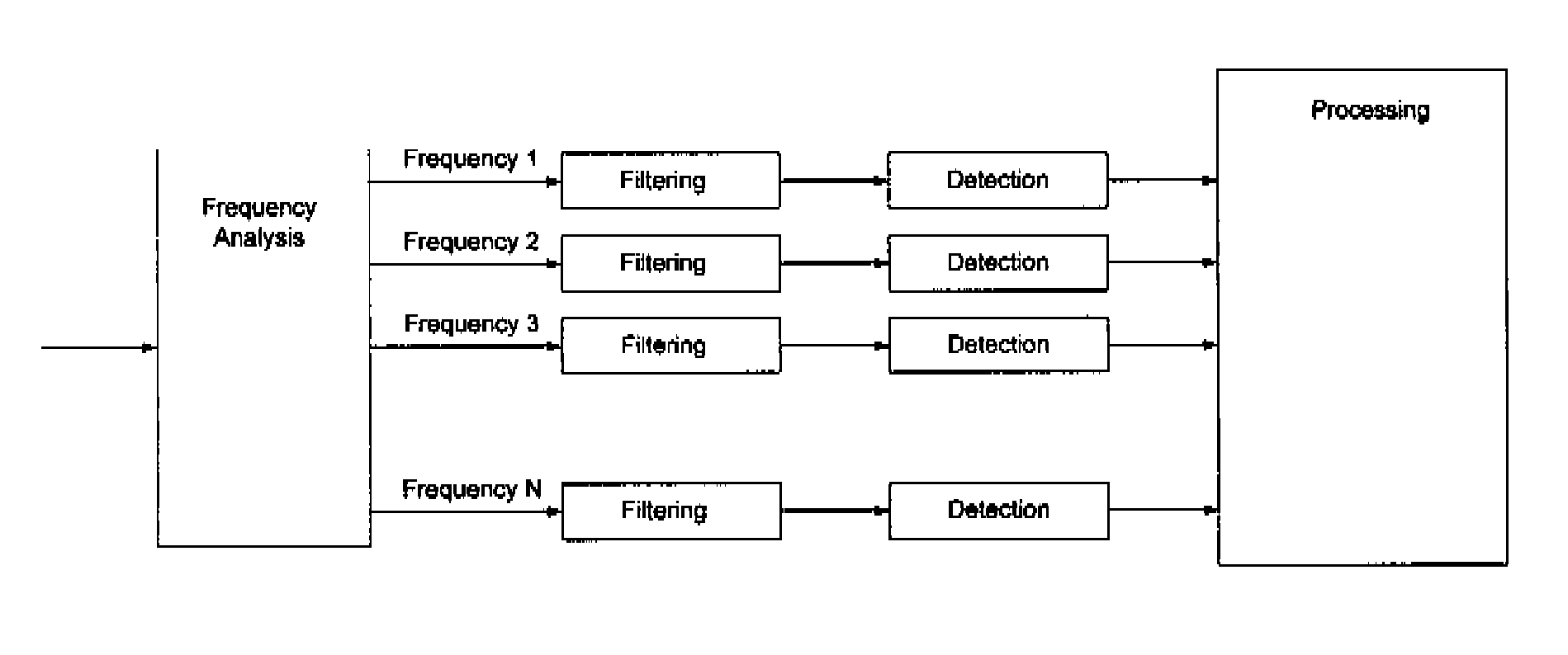
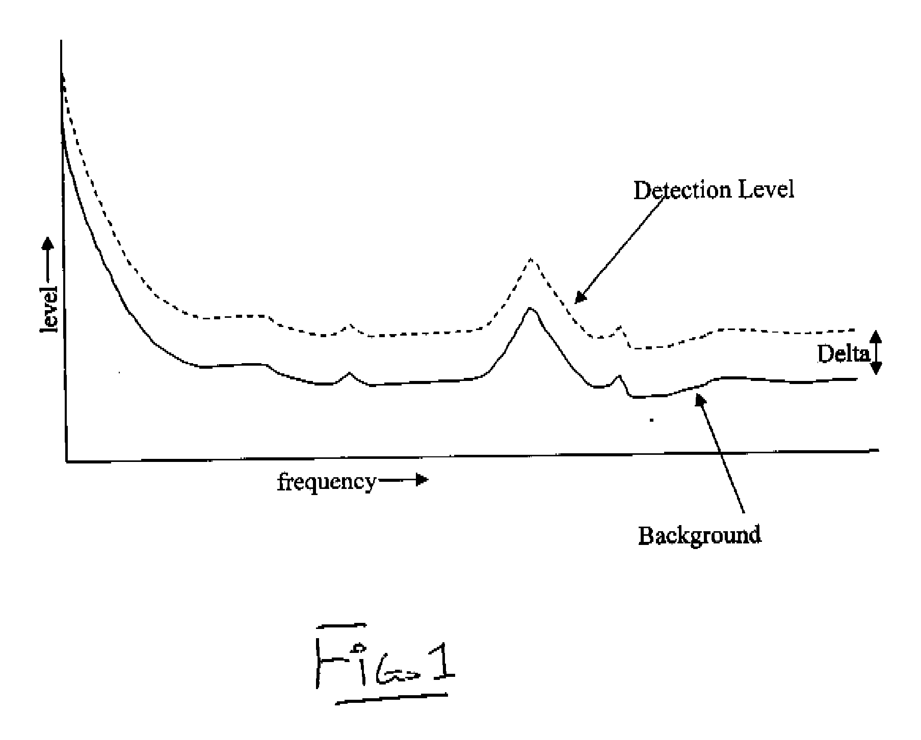
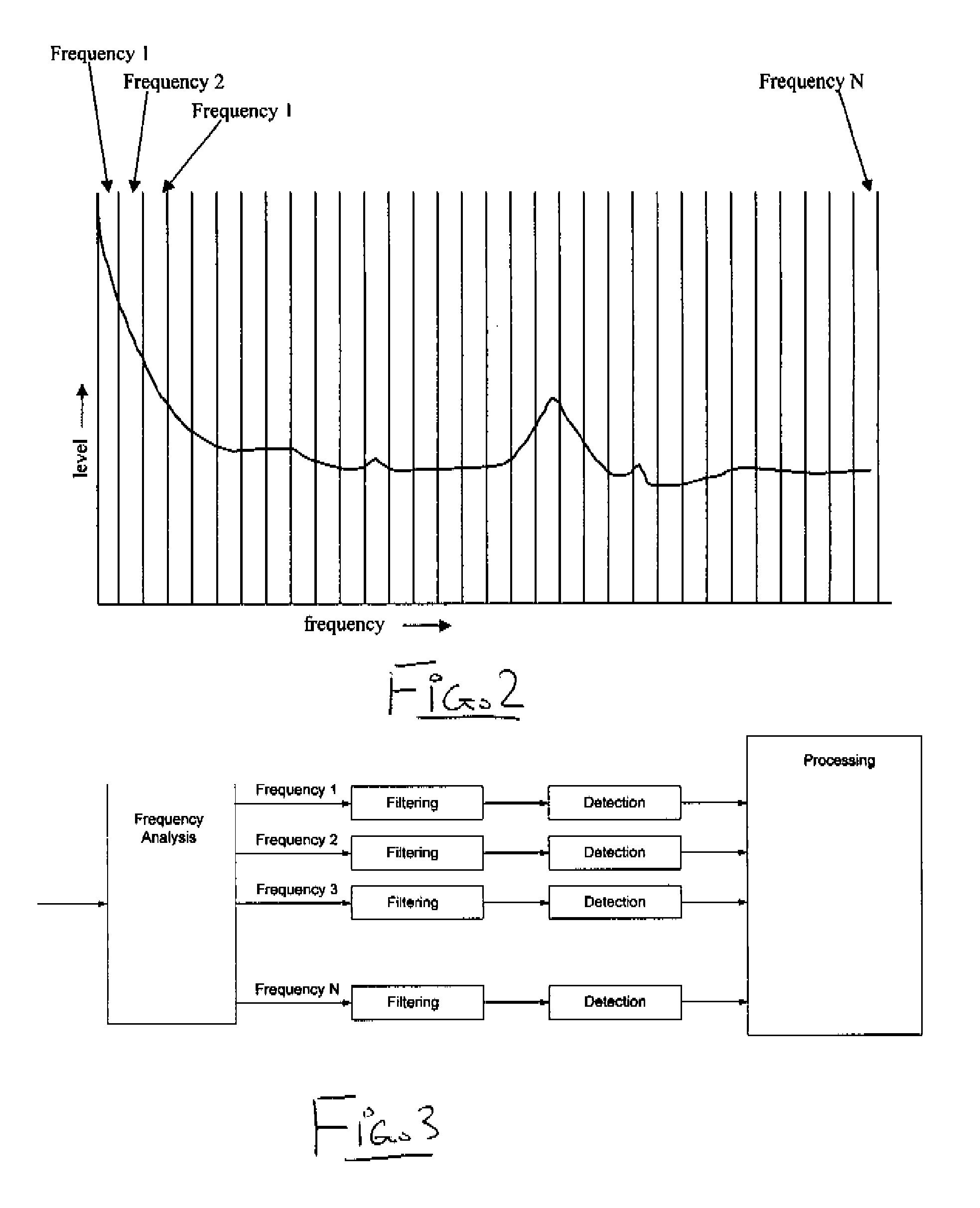
[0040] In FIG. 1 is shown a graph of the Frequency Envelope in which the method of the invention samples data from an A / D converter which is monitoring the signal to be analyzed. The sample stream is divided in to equal length pieces, and then transformed with a Fourier Transform (FT) algorithm. This creates a three dimensional dataset consisting of frequency domain amplitude, frequency, and time. The Frequency Envelope shown in FIG. 1 is calculated by taking the maxima over the time dimension, leaving a two dimensional frequency domain amplitude vs frequency dataset as shown. Additionally, a constant delta is additively or multiplicatively applied to each frequency amplitude element to adjust intrusion sensitivity. That is, the delta or difference value is either simply added to the envelope, to define the threshold value or detection level to be exceeded by the next amplitude element value calculated by the algorithm, or the delta or difference value can be applied by a multiplica...


PUM


Abstract

A signal which varies over time is monitored to determine an alarm condition, where the sample stream of digital values from an A / D converter is divided in to equal length pieces and a Fourier Transform (FT) algorithm is used to transform each piece of the stream into a three dimensional dataset including frequency domain amplitude, frequency and time. A Frequency Envelope is calculated by taking the maxima over the time dimension for a period of time, leaving a two dimensional frequency domain amplitude vs frequency dataset which is compared with new data arriving to determine the alarm condition for each element of the Frequency Envelope either by applying a constant delta additively or multiplicatively or by using a “leaky bucketalgorithm.

Description

[0001] This application claims the benefit of the priority date under 35USC119 from Provisional Application 60 / 704,914 filed 3 Aug. 2005.[0002] The present invention relates to signal detection algorithms as used in, but not limited to, physical fiber optic intrusion detection systems. BACKGROUND OF THE INVENTION [0003] In the following patent applications all filed Jun. 15, 2005 of the present applicant are disclosed and claimed techniques for monitoring single mode fibers for intrusion: [0004] Application Ser. No. 11 / 152,679 entitled AN INTRUSION DETECTION SYSTEM FOR USE ON SINGLE MODE OPTICAL FIBER USING FRESNEL REFLECTIONS. [0005] Application Ser. No. 11 / 152,772 entitled AN INTRUSION DETECTION SYSTEM FOR USE ON SINGLE MODE OPTICAL FIBER USING A STORAGE REGISTER FOR DATA. [0006] Application Ser. No. 11 / 152,680 entitled AN INTRUSION DETECTION SYSTEM FOR USE ON SINGLE MODE OPTICAL FIBER USING A SIMPLIFIED POLARIMETER. [0007] Application Ser. No. 11 / 152,663 entitled AN INTRUSION DET...

Claims


Application Information

Patent Timeline
Patent Type & Authority Applications(United States)
IPC IPC(8): H04B10/08
CPCH04B10/00
Inventor MURPHY, CARY R.GOERTZEN, DANIEL M.BRIDGES, MARK K.VOKEY, DAVID E.
Owner NETWORK INTEGRITY SYST
Learn More