Computer apparatus, storage apparatus, system management apparatus, and hard disk unit power supply controlling method

a computer and storage device technology, applied in the field of computer equipment, storage equipment, system management equipment, and hard disk unit power supply controlling methods, can solve the problems of significant risk of data loss or theft, the large-capacity storage system that has come into widespread use instead of the tape device, and the inability to meet the desire to allow prompt access to stored data, etc., to prolong the life of the hard disk loaded, minimize performance deterioration, and save power

Inactive Publication Date: 2007-04-05
HITACHI LTD
View PDF5 Cites 67 Cited by
  • Summary
  • Abstract
  • Description
  • Claims
  • Application Information

AI Technical Summary

Benefits of technology

[0016] According to the present invention, it is possible to provide a storage apparatus capable of minimizing a performance deterioration, saving the power and prolonging the lifetime of the hard disk loaded to the apparatus to enhance the reliability of the apparatus.

Problems solved by technology

A tape device that has been hitherto used as data storing means for storing a large volume of data no longer satisfies a desire to allow prompt accesses to the stored data.
Meanwhile, the tape device encounters a problem in that high fault rates occur and there is a significant risk that data is lost or stolen during the conveyance of a tape medium.
However, the large-capacity storage system that has come into widespread use instead of the tape device is inferior to the tape device in power consumption.
Some recent reports reveal that the storage system consumes about 20 to 30% of the power in a data center, so how to save the power used for the apparatus becomes one of the biggest challenges for the future.
This leads to a problem in that it is difficult to respond to an access request from a computer without delay and a power-saving effect is not so large.
There is no description about how to prevent the loss of reliability of the individual hard disks due to the repeated on / off operations of the power supply.
The related art of U.S. Pat. No. 2,004,0054939 (see http: / / www.copansys.com / pdfs / Revolution2000TDataSheet.pdf) has a problem in that even when the requisite number of operating hard disks is less than ¼ of the loaded hard disks, it is impossible to expect a power-saving effect as high as an effect attained when the number of operating hard disks is far less than ¼ of the loaded hard disks.
In addition, several hard disks that always operate are provided for responding to the access request without delay, resulting in the increase in power consumption.
Hence, it is difficult to respond to the access request without delay.
There is no description about how to prevent the loss of reliability of the individual hard disks due to the repeated on / off operations of the power supply.

Method used


Image

  • Computer apparatus, storage apparatus, system management apparatus, and hard disk unit power supply controlling method
  • Computer apparatus, storage apparatus, system management apparatus, and hard disk unit power supply controlling method
  • Computer apparatus, storage apparatus, system management apparatus, and hard disk unit power supply controlling method

Examples


first embodiment

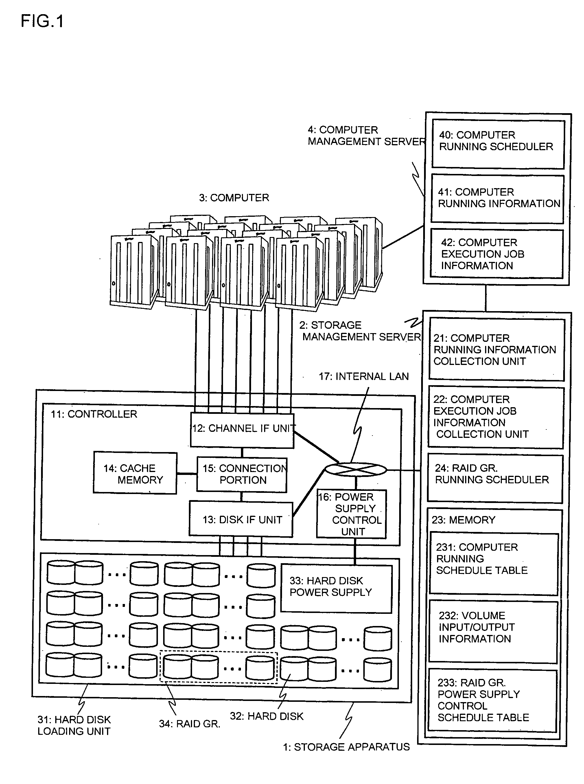
[0034] A first embodiment of the present invention is described below. FIG. 1 shows a configuration example of a system including a storage apparatus according to the first embodiment of the present invention. The system includes a storage apparatus 1, a storage management server 2, a computer 3, and a computer management server 4. The storage management server 2 and the computer management server 4 constitute a system management apparatus. As shown in FIG. 1, the storage apparatus 1 and the computer 3 are directly connected but may be connected through a switch. One or more computers 3 may be provided and composed of a plurality of virtual machines.

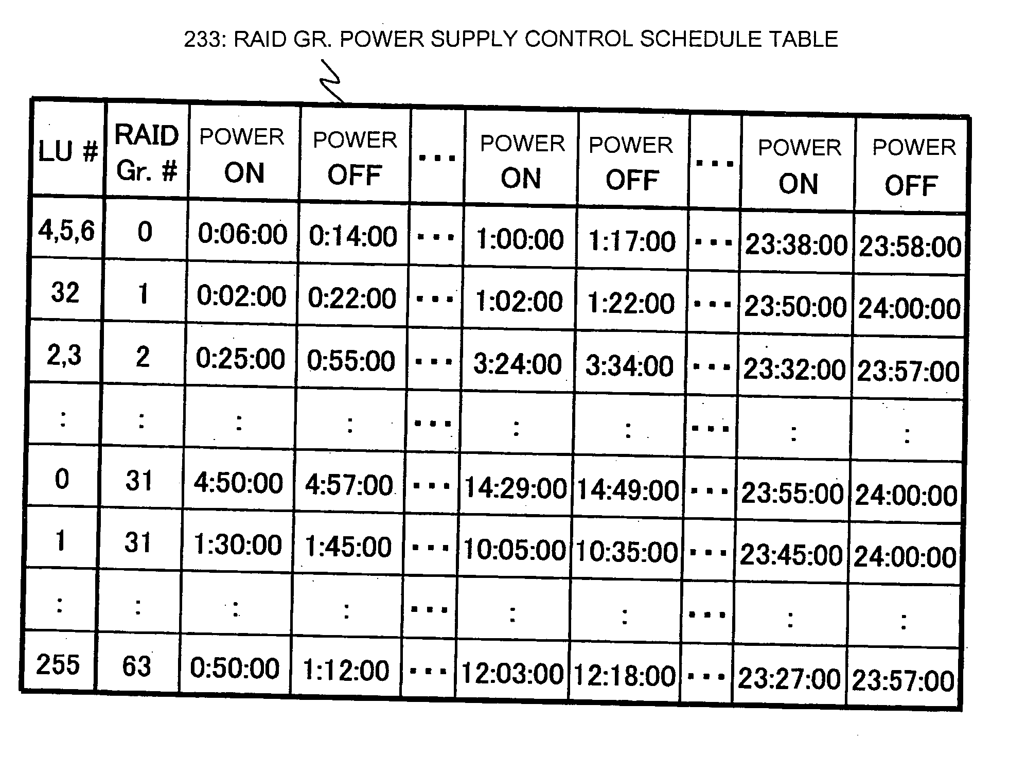
[0035] The storage apparatus 1 includes a controller 11 and a hard disk loading unit (hard disk unit) 31. The controller 11 includes a channel IF (interface) unit 12 connected to the computer 3 to control data write / read accesses from the computer 3, a disk IF (interface) unit 13 connected with a plurality of hard disks 32 to control da...

second embodiment

[0106] Subsequently, a second embodiment of the present invention is described. In this embodiment, the storage management server 2 allocates the logical volumes to each computer 3. The logical volumes are retrieved from the RAID Gr. composed of the plurality of hard disks 32 and allocated to the computers 3. Therefore, after the logical volumes are allocated to the computers 3, the computer-volume (LU)-RAID Gr. mapping 235 as shown in FIG. 4 can be created.

[0107] Based on this table, when one or more pairs of computers simultaneously operate, it is possible to determine how may RAID Gr. are simultaneously operated and which RAID Gr. is simultaneously operated. This determination is carried out for all the combinations of computers, so the combinations of the computers can be retrieved when the RAID Gr. larger than a predetermined number of RAID Gr. simultaneously operate. FIG. 15 is a table showing an example of the retrieval result. A simultaneous running RAID Gr.-computer combin...


PUM


Abstract

To provide a storage system capable of minimizing a performance deterioration, saving power consumption, and realizing a high reliability. A storage system according to the present invention includes a computer, a storage apparatus 1 connected with the computer, and a storage management apparatus connected to the storage apparatus, the storage apparatus including a hard disk unit to control a data write operation and a data read operation between the computer and the hard disk unit, and control on/off states of power supply of the hard disk unit on a group basis, and the system management apparatus collecting running information about the computer and computer execution job information for each computer, and determining an on/off time of the power supply of the hard disk unit on the group basis to record the collected information and the on/off time of the power supply on the group basis.

Description

[0001] The present application is based on and claims priority of Japanese patent application No. 2005-288142 filed on Sep. 30, 2005, the entire contents of which are hereby incorporated by reference. BACKGROUND OF THE INVENTION [0002] 1. Field of the Invention [0003] The present invention relates to a storage apparatus system (hereinafter also referred to as a “storage system”) for storing data of a computer (hereinafter also referred to as a “server”). In particular, the present invention relates to a storage apparatus composed of a plurality of hard disk units and a technique of controlling a power supply of the plurality of hard disk units. [0004] 2. Description of the Related Art [0005] In recent years, various kinds of companies have found it necessary to save all business documents or electronic mail in a storage system under various laws and regulations, and in addition, to enable prompt accesses to the stored data as needed. [0006] A tape device that has been hitherto used ...

Claims


Application Information

Patent Timeline
Patent Type & Authority Applications(United States)
IPC IPC(8): G06F1/26
CPCG06F1/3221G06F1/3268G06F3/0625Y02B60/32G06F3/0665G06F3/0689Y02B60/1246G06F3/0634Y02D10/00Y02D30/50
Inventor FUJIMOTO, KAZUHISA
Owner HITACHI LTD
Why Eureka
Try Eureka