Methods and apparatuses relating to block receptor configurations and block assembly processes

a technology of block receptors and configurations, applied in the field of fabrication openings, can solve the problems of increasing the number of ics to be packaged, presenting problems that the overall process has to overcome, and improving the efficiency or yield of the receptor site filling process

Inactive Publication Date: 2007-04-12
RUIZHANG TECH LTD CO
View PDF2 Cites 17 Cited by
  • Summary
  • Abstract
  • Description
  • Claims
  • Application Information

AI Technical Summary

Benefits of technology

[0018] The invention also teaches an embodiment where a receptor site opening consists of various depths formed from a substrate with a block receptor site of maximum depth in one part of the opening and an exit ramp immediately adjacent to the block receptor site that rises from one side of the block receptor site and extends to the opposite edge of the opening. This receptor site opening can be used in conjunction with the existing FSA process. In the process, the substrate containing receptor opening sites is oriented at an incline with the exit ramps of the receptor site openings pointing downhill and the block receptor sites in the uphill direction. During block deposition onto the substrate, the blocks that land right-side-up and slide into block receptor sites will stay and remain, while any excess blocks or inverted blocks or improperly positioned blocks will not anchor inside the block receptor sites, but slide over the receptor site and out of the receptor site opening via the exit ramp. This embodiment takes advantage of the gravitational forces acting on the blocks by the inclined angle to clear and remove excess or inverted blocks.
[0019] Yet another embodiment of the present invention teaches a receptor site opening consisting of different depths formed from a substrate. In one example, there are at least two recesses of different depths located adjacently, side by side in parallel, where a deeper recess is both longer and wider than a shallower recess and forms a block receptor site at a region not bordering the shallower recess. In another example of this embodiment, there are three recesses of different depths. The shallow recess is shorter and narrower than the deeper recess which is located adjacently, side by side in parallel to the deeper recess, similar to the previous example. However, a third deepest recess, also referred to as the block receptor site, is formed at the region continuing from along the deeper recess at the end that does not share a common side wall with the shallow recess. Both of these examples may be used in combination with a clearing device mechanism to remove excess and improperly oriented blocks and move correctly seated blocks into the receptor site location. The device mechanism usually consists of a brush, static or rotating foam roller, mechanical wiper or blade. The block clearing can be accomplished in three steps after the blocks are deposited onto the substrate. First, a wiper sweeps along the widthwise direction from the deeper recess towards the shallow recess to remove any blocks that are excess or improperly placed. Second, another wiper pushes the properly seated blocks in the deeper recess along the lengthwise direction towards the block receptor site so that one block can be positioned exactly at the block receptor site. Lastly, either the first wiper or a different wiper sweeps from the shallow recess towards the deeper recess in the widthwise direction to clear any remaining properly seated but excess blocks in the deeper recess. This last step allows the wiper to take advantage of the partial depth created by the shallow recess to get partly into the receptor site opening and remove the excess blocks, while leaving exactly one block in the block receptor site.

Problems solved by technology

As these electronic devices advance to become more complex or as consumers or applications demand a size reduction of these electronic devices, the demands to package smaller ICs also increase.
Despite its efficiency over pick and place methods, the stochastic nature of FSA presents problems that the overall process has to overcome.
However, the improvement still does not improve the efficiency or yield of the receptor site filling process.
Part of the problem is due to the density ratio of the blocks relative to the receptor sites, the lubricity of the fluid and surfaces, or simply that the blocks were dislodged from the receptor sites after having been properly deposited into the receptor sites.
When functional block elements are not deposited into the receptor sites or are improperly placed into the receptor sites, it prevents proper execution of subsequent manufacturing steps and leads to inefficiency of the entire process.
Improperly placed blocks, excess blocks or absence of blocks in receptor sites lowers the overall production yield.
However, repeated application of the FSA process adds processing time and in some cases requires larger processing equipment or additional functional blocks, therefore it is not considered an overall cost effective solution.

Method used


Image

  • Methods and apparatuses relating to block receptor configurations and block assembly processes
  • Methods and apparatuses relating to block receptor configurations and block assembly processes
  • Methods and apparatuses relating to block receptor configurations and block assembly processes

Examples


Embodiment Construction

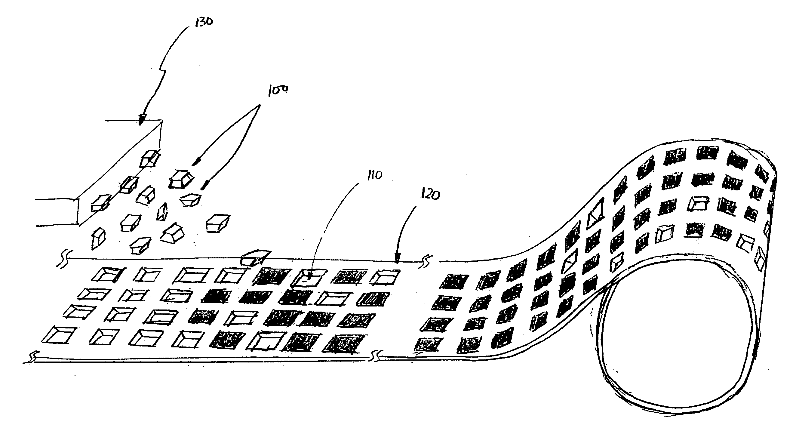
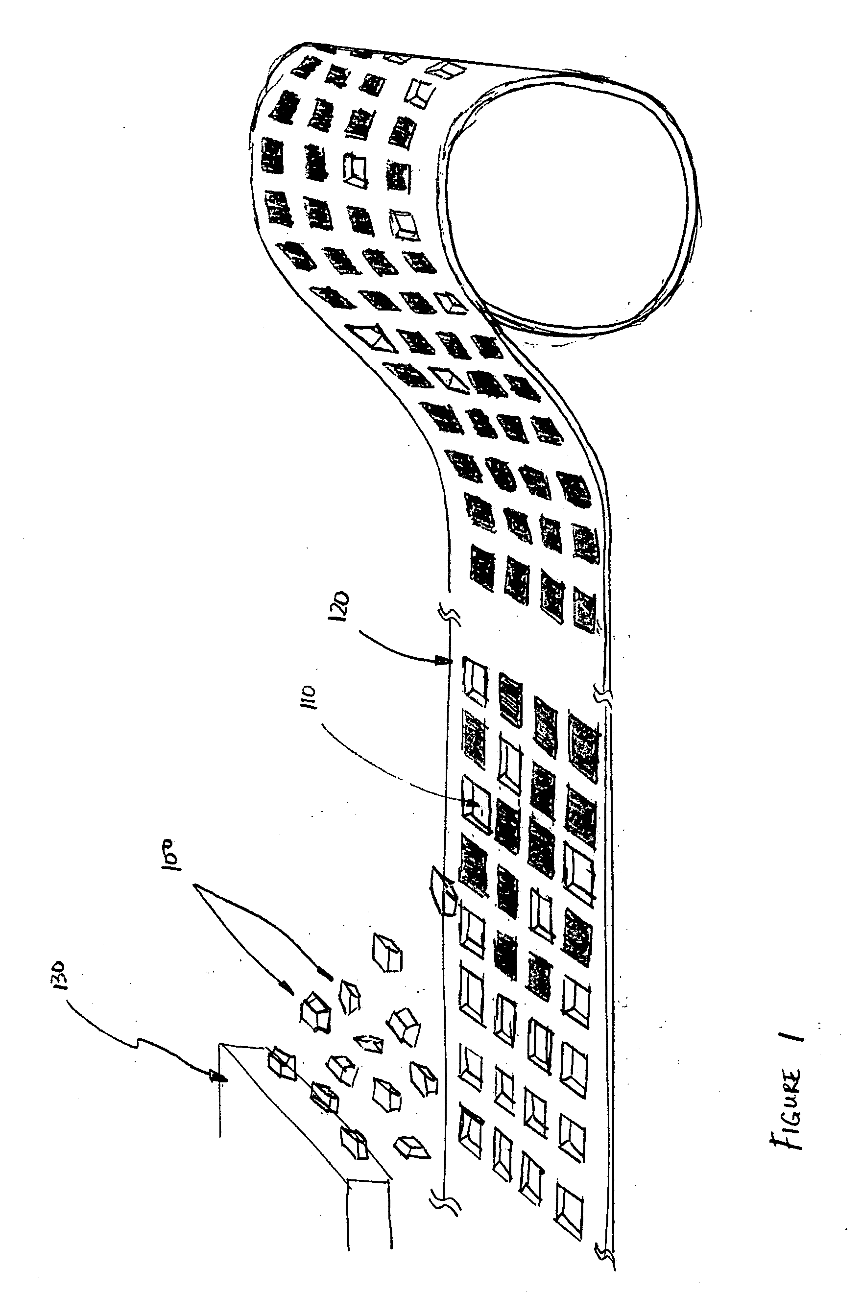
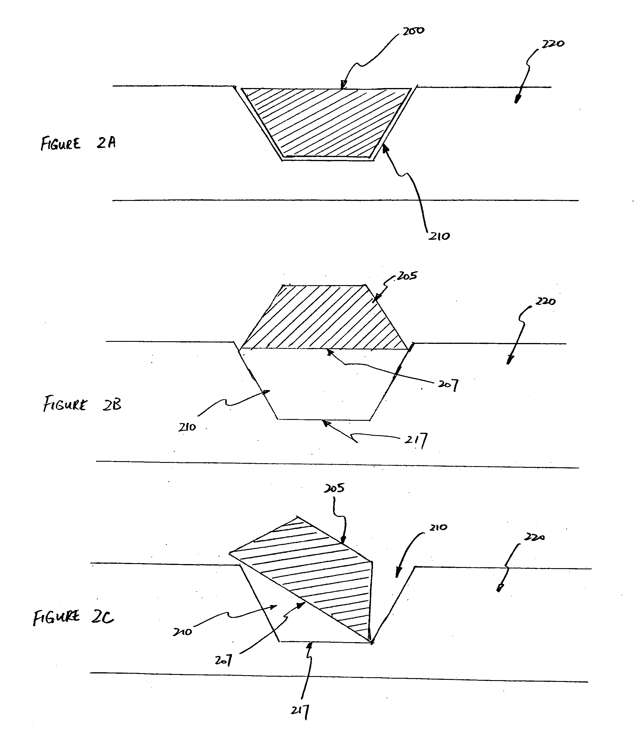
[0045] The present invention relates to apparatuses and methods for shaping receptor openings to improve the efficiency of depositing functional elements into an array of receptor sites in a receiving substrate, or a long web of repeated substrate elements, via a FSA process. The following descriptions and drawings are illustrative of the invention by example and are not to be construed as limiting the invention. Numerous details are described to provide a thorough understanding of the present invention. In certain instances, well-known or conventional details are not described in order to not unnecessarily obscure the present invention in detail.

[0046] The present invention relates generally to the field of shaping openings in a receiving substrate and to apparatuses having these openings. The present invention may be used to shape openings for different types of arrays. Generally an element in an array includes a functional component that may include an electrical component, a ch...


PUM


Abstract

The present invention approaches the filling efficiency problem from the perspective of the block receptor sites independent of any modification to existing manufacturing equipment or general block geometry. The present invention teaches the use of receptor site openings consisting of various shapes to increase the filling efficiency by improving the ease with which a right-side-up block can deposit into a receptor site opening while preventing improperly oriented blocks from completely entering the block receptor site and enhancing the ease with which incorrectly seated and upside down blocks can be removed from the receptor site.

Description

[0001] This application claims benefit and priority to provisional application 60 / 724,481 filed on Oct. 7, 2005. The full disclosure of the provisional application is incorporated herein in its entirety.GOVERNMENT RIGHTS NOTICE [0002] This invention was made with government support with at least one of these contracts with North Dakota State University: subcontract SPP002-04, H94003-04-2-0406 (prime); subcontract 4080, DMEA90-01-C-0009 (prime); subcontract SB004-03, DMEA90-03-3-0303 (prime); and subcontract 5038, DMEA90-02-C-0224 (prime). The Government has certain rights to this invention.FIELD [0003] The present invention relates generally to the field of fabricating openings in a substrate which are used for depositing block elements. In particular, the present invention relates to the shaping of the openings in a substrate which are designed to receive an element which is a block that consists of at least one functional element. More specifically, various embodiments of the pres...

Claims


Application Information

Patent Timeline
Patent Type & Authority Applications(United States)
IPC IPC(8): E04C1/39E04B5/48
CPCG06K19/07718G06K19/07749H01L24/95H01L2224/95085H01L2224/95122H01L2224/95136H01L2924/01013H01L2924/01029H01L2924/01075H01L2924/10158H01L2924/14H01L2924/15155H01L2924/15156H01L2924/15157H01L2924/15165H01L2924/15153H01L2924/01006H01L2924/01023H01L2924/01033H01L2924/351H01L2924/00
Inventor SCHATZ, KENNETH DAVID
Owner RUIZHANG TECH LTD CO
Why Eureka
Try Eureka