System, method, and apparatus for accessing outlets in a two-stage diverter spool assembly

a diverter spool and outlet technology, applied in the field of diverter spools, can solve the problems of inability to handle the higher pressure of blowout preventers, limited flow outlets, and significant down time and cost associated with the removal of diverters, and achieve the effect of saving rig time operations

Active Publication Date: 2007-04-12
VETCO GRAY LLC
View PDF18 Cites 20 Cited by
  • Summary
  • Abstract
  • Description
  • Claims
  • Application Information

AI Technical Summary

Benefits of technology

[0008] In one embodiment, the outlets on the two-stage diverter spool allow for cuttings / mud flow to be diverted to the mud pits without passing them through the BOP stack. These outlets are used, for example, when drilling through formations that do not require BOP control. The two-stage diverter spool allows for the wellhead, riser, and BOP stack to be installed at one time to save rig time operations.

Problems solved by technology

The mud flow outlets are limited to low pressure or uncontrolled applications and are incapable of handling higher pressures associated with blow out preventers (BOPs).
Unfortunately, the down time and cost associated with the removal of the diverter can be significant.

Method used


Image

  • System, method, and apparatus for accessing outlets in a two-stage diverter spool assembly
  • System, method, and apparatus for accessing outlets in a two-stage diverter spool assembly
  • System, method, and apparatus for accessing outlets in a two-stage diverter spool assembly

Examples


Embodiment Construction

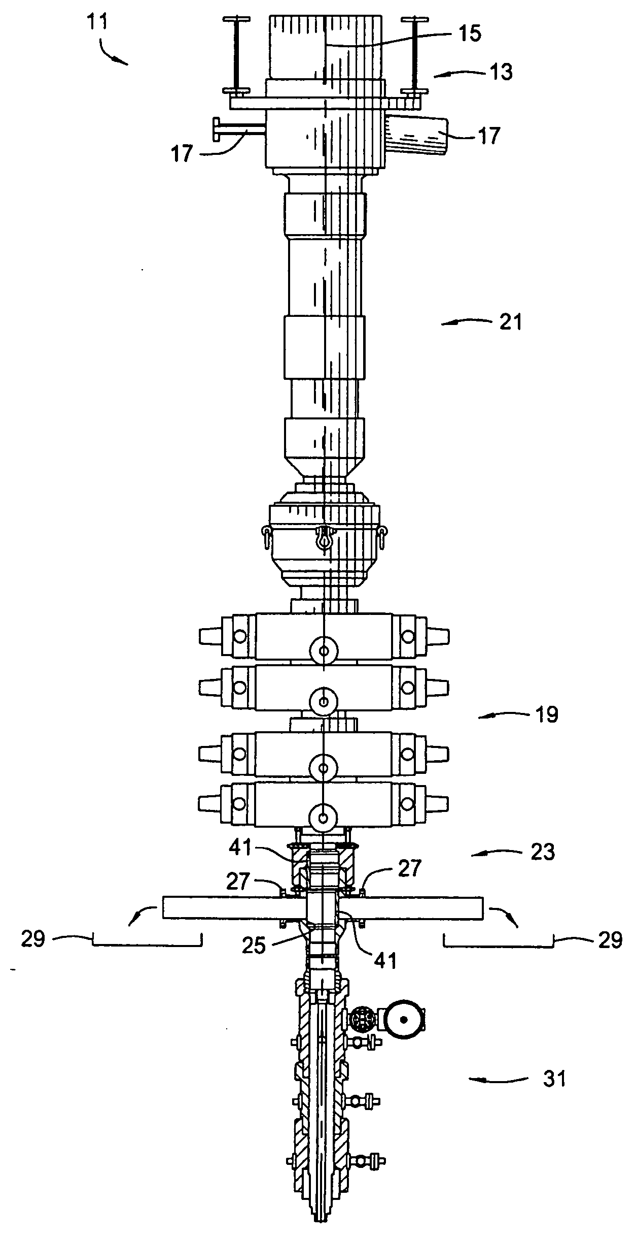
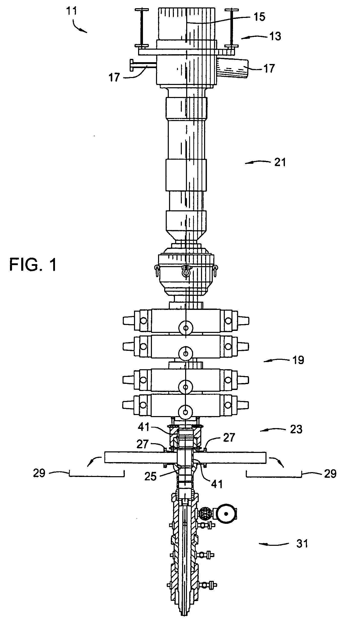
[0016] Referring to FIGS. 1-5, one embodiment of an improved system, method, and apparatus for selectively opening and closing outlets or “low pressure” outlets in two-stage diverter spools is shown. FIG. 1 depicts a wellhead system 11 comprising an upper diverter 13 having an axis 15 and additional or “high pressure” outlets 17. A blowout preventer, or BOP 19, is mounted axially below the upper diverter 13. An optional overshot mandrel 21 is located between the upper diverter 13 and the BOP 19. A lower diverter 23 is mounted axially below the BOP 19. The lower diverter 23 has an axial bore 25 and low pressure outlets 27 extending from the axial bore 25 to mud pits 29 for discharging drilling mud therefrom. A wellhead housing assembly 31 is mounted axially below the lower diverter 23.

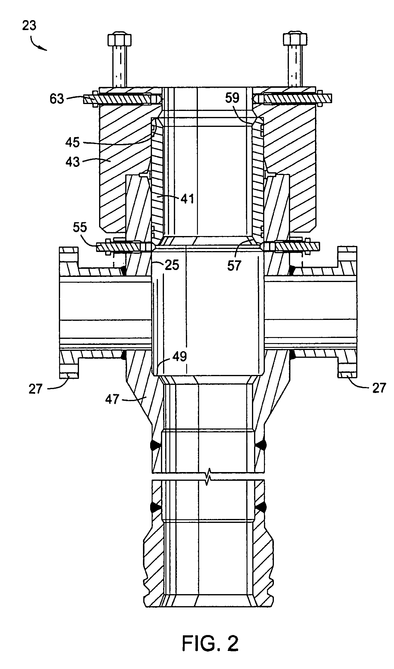
[0017] Referring now to FIGS. 2-5, a sleeve 41 is located in and axially movable relative to the axial bore 25 of the lower diverter 23. The sleeve 41 has an open position (left side of FIG. 1 and FIGS...


PUM


Abstract

A wellhead system diverter spool contains an internal sleeve that can be axially shifted internal to the spool with a handling tool. The sleeve permits access to outlets in the spool when required. When higher pressures are required, the internal sleeve is shifted downward to close off access to the outlets without change out of equipment or changing the BOP stack riser system. The low pressure lines connected to the outlets can remain installed but are isolated from the higher pressure BOP stack pressures.

Description

BACKGROUND OF THE INVENTION [0001] 1. Technical Field [0002] The present invention relates in general to diverter spools and, in particular, to an improved system, method, and apparatus for selectively opening and closing low pressure or uncontrolled outlets in two-stage diverter spools. [0003] 2. Description of the Related Art [0004] Diverters are mounted to drilling rigs below the rig floor for use throughout the various stages of drilling. A support housing typically mounts below the rig floor and has a lateral flowline outlet for directing mud flow. The housing is a tubular member with an axial bore. A diverter body is secured to the upper end of a riser, is lowered through the rotary table, and lands in the housing. The diverter body has lateral flow openings that are axially aligned with the lateral flowline outlet. A pair of seals are usually located above and below the lateral flowline outlet. [0005] The mud flow outlets are limited to low pressure or uncontrolled applicatio...

Claims


Application Information

Patent Timeline
Patent Type & Authority Applications(United States)
IPC IPC(8): E21B21/00
CPCE21B21/106E21B33/038
Inventor BORAK, EUGENE A.
Owner VETCO GRAY LLC
Why Eureka
Try Eureka