Sputtering device

a technology of sputtering device and film, which is applied in the direction of electrolysis components, vacuum evaporation coatings, coatings, etc., to achieve the effect of increasing the film thickness distribution in the whole of the substra

Inactive Publication Date: 2007-04-12
CYG CORP
View PDF8 Cites 15 Cited by
  • Summary
  • Abstract
  • Description
  • Claims
  • Application Information

AI Technical Summary

Benefits of technology

[0015] According to the above constitution, since the sputtering cathode unit in which the plural sputtering cathodes are arranged so as to face to an approximately center position of the substrate can be rotated around a center axis of the substrate, every target can be sputtered in turns, so that an effect such that film thickness distribution can be increased is achieved.
[0016] Besides, it is possible to sputter every target simultaneously, and thus, an effect such that alloy thin film with good alloy degree in a film thickness direction can be formed is achieved.
[0017] Furthermore, according to providing the means for modifying distribution on the opening end portion of every sputtering cathode, sputtering particles in a center portion of the opening end portion can be restricted, so that it is possible to increase film thickness distribution.
[0018] Moreover, according to constituting the means for modifying distribution by the round metal plate having a diameter about half of the target and the supporting portion supporting the round metal plate and providing the notch portion on the position at the center axis side of the substrate, sputtering particles can be increased in the substrate center axis side of the slant sputtering cathode, so that the film thickness distribution in the whole of the substrate can be increased.
[0019] Besides, according to constituting the means for modifying distribution by the columnar portion having the bottom surface with the diameter about half of the target and extending with the specific length along the center axis of the target and the supporting portion supporting the columnar portion, a thick portion of the film thickness by the slant sputtering cathode unit can be smoothed, so that film thickness distribution in the whole of the substrate can be improved.

Problems solved by technology

As seen from the above references, it was a usual large problem how to increase distribution of the film thickness on the substrate, and thus, various plans were carried out.

Method used


Image

  • Sputtering device
  • Sputtering device
  • Sputtering device

Examples


Embodiment Construction

[0027] Hereinafter, the embodiments of this invention were explained by referring drawings.

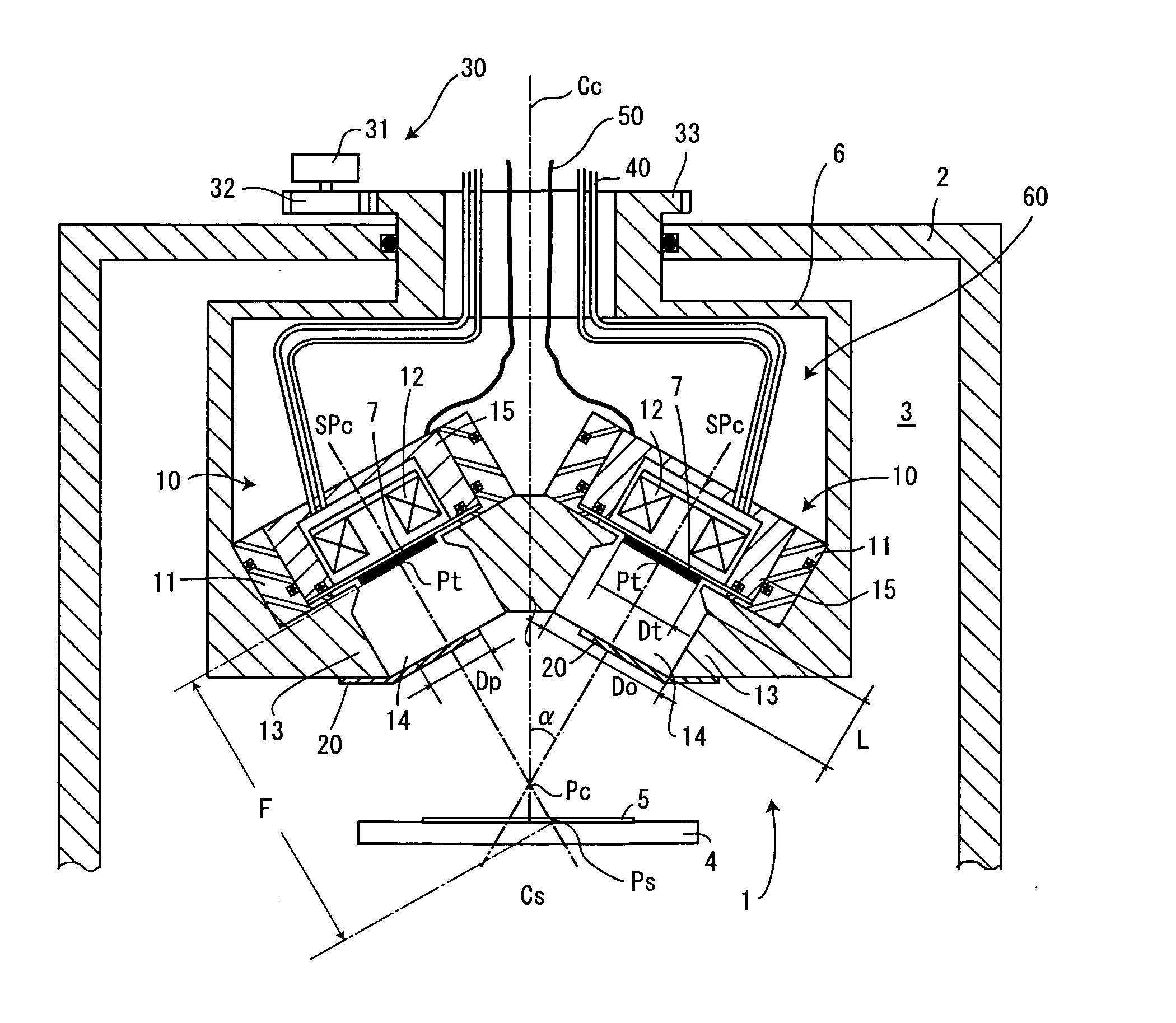
[0028] A sputtering device 1 shown in FIG. 1 is constituted of at least a vacuum container 2 defining a sputtering space 3, a substrate holder 4 holding a substrate 5 in the sputtering space 3, a sputtering cathode unit 60 held rotatably in the vacuum container 2 and a driving mechanism rotating the sputtering cathode unit 60.

[0029] The sputtering cathode unit 60 is constituted of a cathode block installed rotatably in a condition that sealing is held by a means such as an O-ring to the vacuum container 2 and plural sputtering cathodes 10 arranged in the cathode block 6. Furthermore, in the cathode block 6, radiation holes 14 are formed corresponding to the sputtering cathodes respectively so as to face the substrate 5. Note that the fringe of each radiation holes 14 is defmed as a hood portion 13. Besides, reference number 40 illustrated in the cathode block 6 indicates pipes for introducin...


PUM

PropertyMeasurementUnit
angleaaaaaaaaaa
angleaaaaaaaaaa
angleaaaaaaaaaa

Abstract

A sputtering device according to the present invention comprises at least a vacuum container, a substrate holder arranged in the vacuum container, plural sputtering cathodes each of which has a target for sputtering to a substrate installed on the substrate holder, wherein the plural sputtering cathodes are arranged so that center axes of the targets installed on the sputtering cathodes is inclined at specific angle against an axis of the substrate installed on the substrate holder, and a sputtering cathode unit constituted of the plural sputtering cathodes is held to the vacuum container rotatably around the axis of said substrate.

Description

BACKGROUND OF THE INVENTION [0001] The present invention relates to a sputtering device having a plurality of sputtering cathodes which have targets for forming a thin film on a substrate respectively, wherein atoms or molecules of the targets are sputtered by means of colliding ionized gas to the targets to adhere them to the substrate. [0002] JP 2002-20864 A discloses a sputtering device having a plurality of targets installed on respective cathodes and a substrate rotation device for rotating the round substrate on which the film should be formed around its center, wherein the plural targets are parallel to a surface of the substrate and centers of the plural targets are shifted to a center of the substrate, and further angle between a line extending through a center of target's surface and through a center of substrate's surface and a normal line of the substrate's surface is not less than 40°. [0003] JP 2003-166055 A discloses a film forming device having a rotation substrate a...

Claims


Application Information

Patent Timeline
Patent Type & Authority Applications(United States)
IPC IPC(8): C23C14/00
CPCC23C14/352H01J37/3408H01J37/3455
Inventor TAKAHASHI, NOBUYUKI
Owner CYG CORP
Why Eureka
Try Eureka