
Magnetic transmitter and receiver for a tire pressure monitoring system

Inactive Publication Date: 2007-04-12
HONDA MOTOR CO LTD
View PDF6 Cites 10 Cited by
  • Summary
  • Abstract
  • Description
  • Claims
  • Application Information

AI Technical Summary

Benefits of technology

[0005] The present invention provides a simple, inexpensive system for continuously monitoring tire pressure from individual vehicle wheels. The system transfers a small amount of data with each revolution of the vehicle wheel. Data is transferred from each wheel or tire to the vehicle body and then to a centralized control unit.
[0008] The system is an improvement over the prior art. By transferring a single pulse of data of a size of one bit, there is less of a chance of error in transfer. Additionally, one or more of each eight pulses transferred may be a checking bit or status bit that help confirm the accuracy of the system. Additionally, the strength of the electromagnetic pulse is adjustable and can be optimized to offset electrical noise or tolerance, thereby making the system more robust compared to frequency, stepped pulse, or signal modulation methods used to transfer pressure information.

Problems solved by technology

However, this substitution requires reducing the accuracy of the pressure value transmitted or the amount of status information transmitted.

Method used


Image

  • Magnetic transmitter and receiver for a tire pressure monitoring system
  • Magnetic transmitter and receiver for a tire pressure monitoring system
  • Magnetic transmitter and receiver for a tire pressure monitoring system

Examples


Embodiment Construction

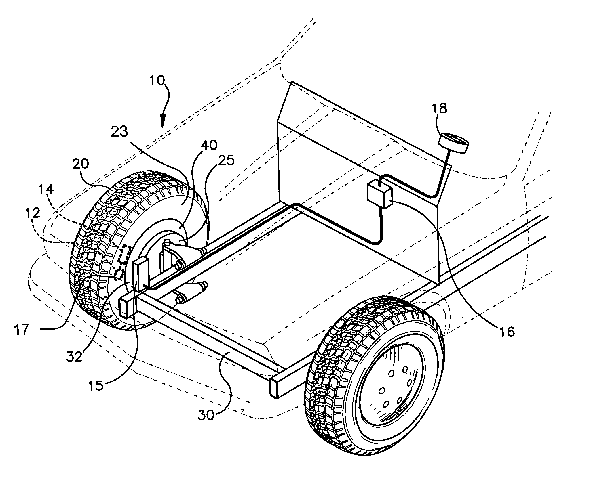
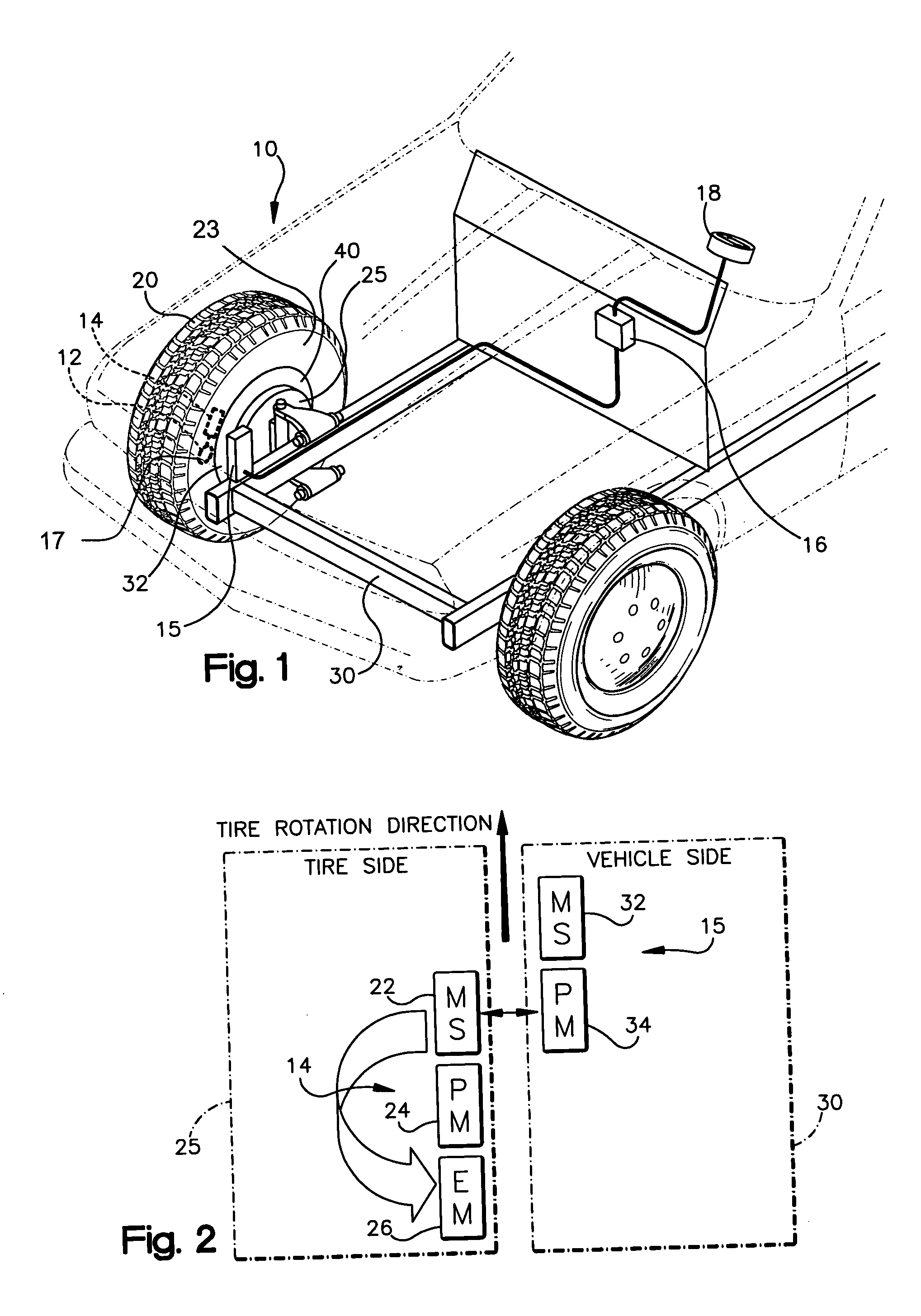
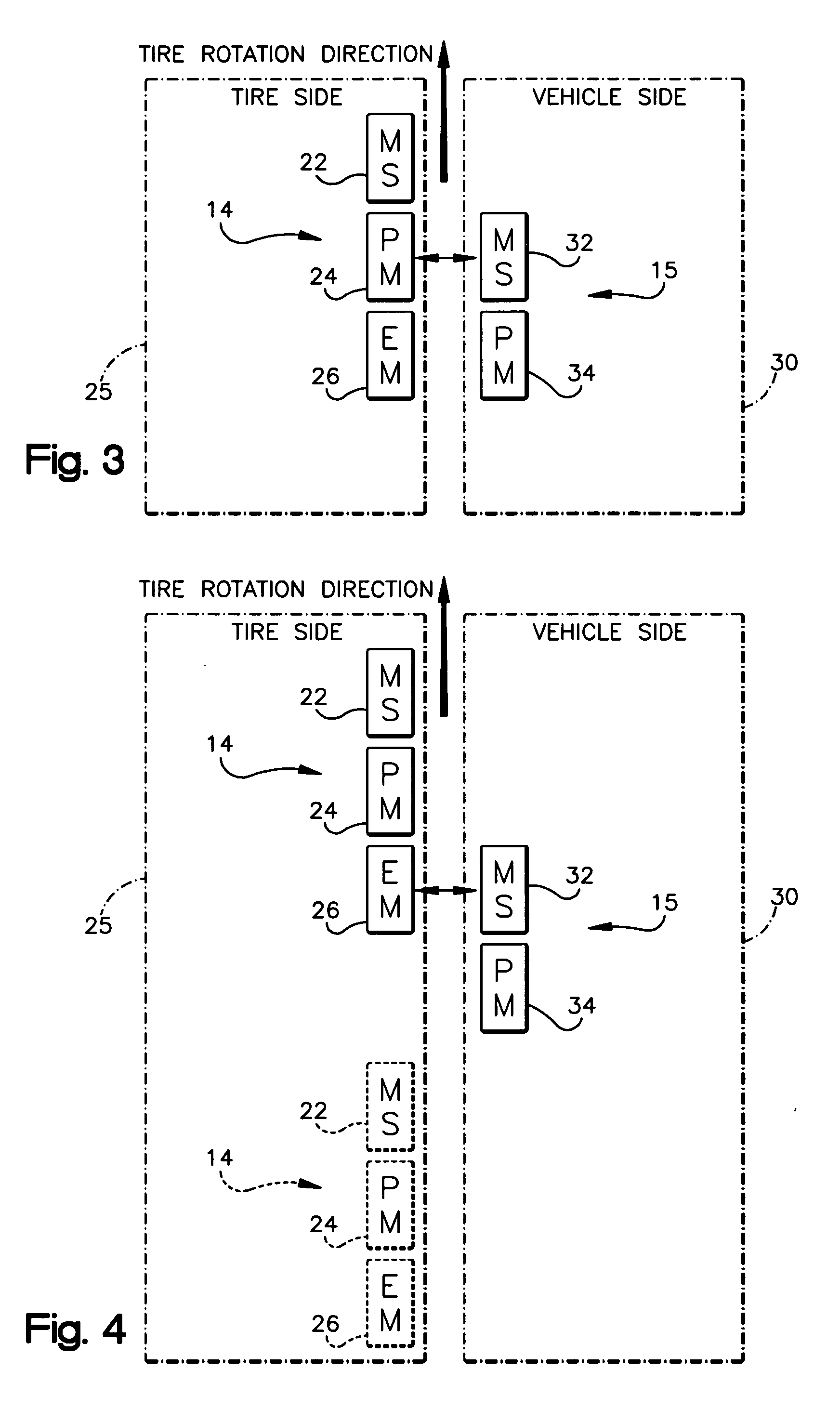
[0015] Referring to FIG. 1, the present invention is directed to a vehicle tire pressure monitoring system 10 including a tire pressure transducer 12, an electromagnet system 14, sensor system 15 for receiving pulses from the electromagnet system 14, an electronic control unit (ECU) 16, and a display 18 for use on vehicles, specifically passenger cars, trucks, sport utility vehicles, etc.

[0016] The tire pressure transducer 12 measures the air pressure within a vehicle tire 20 and provides electrical output having a magnitude in proportion to the measured tire pressure. The pressure transducer 12 is any of a type known by those skilled in the art, such as a piezoelectric or Micro-Electro-Mechanical System (MEMS) transducer. Preferably, the pressure transducer 12 is contained within the tire and attached to the wheel rim 40. Alternatively, the pressure transducer 12 either penetrates the interior of the tire 20 or senses fluctuations in the shape of a designated portion of a tire wal...


PUM


Abstract

A vehicle tire pressure monitoring system and method is provided, the system including a tire pressure transducer affixed to either the tire or wheel of a vehicle. An electromagnet system is in electrical communication with the tire pressure transducer, the electromagnet system configured to generate pulses and transfer a single bit of data to a sensor system on the vehicle body upon each revolution of the tire or wheel. The sensor system in turn transfers the received bits to an electronic control unit wherein the code is converted into a read out for the vehicle operator. One or more bits within the code may be redundant checking bits or bits representing the status of the pressure transducer or electromagnet system.

Description

BACKGROUND OF THE INVENTION [0001] The present invention applies to motor vehicle components and more specifically to components that automatically measure tire pressure and warn the vehicle operator when the tire pressure reaches a dangerously low level. [0002] Systems currently being used for automatic measurement of tire pressure include tire radius monitoring systems, common visual gauges, radio transmitter based systems and proximity transfer based systems. A radius monitoring system uses the vehicle's anti-lock braking system (ABS) to measure the changing radius of a vehicle tire. Logic within the ABS calculates a value for tire pressure based upon the measured tire radius. A radio transmitter based system includes a transmitter upon each vehicle wheel and a centralized receiver on the body of the vehicle. [0003] As an example of a proximity transfer based system, U.S. Pat. No. 6,124,787 to Isakov et al., discloses a tire pressure monitoring system (TPMS) as installed in the d...

Claims


Application Information

Patent Timeline
IPC IPC(8): B60C23/02
CPCB60C23/0408B60C23/0425
Inventor THIELE, STEVEN R.
Owner HONDA MOTOR CO LTD
Learn More