Apparatus and method for constructing a frame to support multilink in multi-hop relay cellular network

Inactive Publication Date: 2007-04-12
SAMSUNG ELECTRONICS CO LTD
View PDF3 Cites 60 Cited by
  • Summary
  • Abstract
  • Description
  • Claims
  • Application Information

AI Technical Summary

Benefits of technology

[0020] An object of the present invention is to substantially solve at least the above problems and/or disadvantages and to provide at least the advantages below. Accordingly, an object of the present inve

Problems solved by technology

In the 4G mobile communication system, it is impossible to implement a centralized network using the existing wireless network design as it is.
However, because the BS is stationary, the cellular network is low in flexibility in construction of a wireless network, which makes it difficult to provide an efficient service in an environment with a great change in traffic distribution or requirements.
Therefore, the frame-in-frame relaying structure may have a short delay and a short round

Method used


Image

  • Apparatus and method for constructing a frame to support multilink in multi-hop relay cellular network
  • Apparatus and method for constructing a frame to support multilink in multi-hop relay cellular network
  • Apparatus and method for constructing a frame to support multilink in multi-hop relay cellular network

Examples


first embodiment

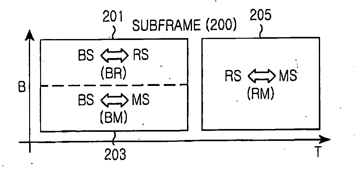
[0045]FIG. 2 illustrates a subframe structure for a multi-hop relay cellular network according to the present invention.

[0046] Referring to FIG. 2, a subframe 200 includes a first section for communication with a BS by a direct link and a second section for communication with the BS by a relay link. The first and second sections are separated by a time slot such that each of the BS, an RS, and an MS can be controlled to receive a signal only in its time section. The first and second sections can be arranged in a reversed order.

[0047] The first section for direct communication with the BS is divided into a BS-RS subframe 201 and a BS-MS subframe 203. The BS-RS subframe 201 and the BS-MS subframe 203 are separately located in the single section (the first section) of the subframe 200 by a subframe-in-subframe scheme and have different bursts. That is, the BS generates the subframe 200 by regarding the RS as an MS.

[0048] Here, the subframes 201 and 203 can be assigned for the bursts ...

second embodiment

[0053]FIG. 3 illustrates a subframe structure for a multi-hop relay cellular network according to the present invention.

[0054] Referring to FIG. 3, a subframe 300 includes a first section for communication with an MS and a second section for communication between a BS and an RS. The first and second sections are separated by a time resource. Further, the first and second sections are separated by a subframe-by-subframe scheme and can be arranged in a reversed order.

[0055] The first section for communication with the MS is divided into an RS-MS subframe 301 and a BS-MS subframe 303. The RS-MS subframe 301 and the BS-MS subframe 303 are separately located in the single section (the first section) of the subframe 300 by a subframe-in-subframe scheme and have different bursts. Since the BS and a plurality of RSs perform transmission using the subframes (the RS-MS subframe 301 and the BS-MS subframe 303) of the first section, a permutation including a dedicated pilot can be used for eac...

third embodiment

[0057]FIG. 4 illustrates a subframe structure for a multi-hop relay cellular network according to the present invention.

[0058] Referring to FIG. 4, a subframe 400 includes a first section and a second section. The first section includes a BS-RS subframe 401 and a BS-MS subframe 403, and the second section includes an RS-MS subframe 405 and a BS-MS subframe 407. The BS-RS subframe 401 and the RS-MS subframe 405 are arranged by a subframe-by-subframe scheme, and the BS-MS subframes 403 and 407 are respectively arranged in the first and second sections by a frame-by-frame scheme. The first and second sections are separated using a time resource and can be arranged in a reversed order.

[0059] The first section for direct communication with the BS is divided into the BS-RS subframe 401 and the BS-MS subframe 403. The BS-RS subframe 401 and the BS-MS subframe 403 are separately located in the single section (the first section) of the subframe 400 by a subframe-in-subframe scheme and have ...


PUM


Abstract

Provided is an apparatus and method for constructing a subframe to support a multi link in a multi-hop relay cellular network. In a first section of a subframe, a subframe for communication with a mobile station (MS) is constructed, and in a next second section of the subframe, a subframe for communication with a relay station (RS) is constructed. Therefore, resources can be efficiently used without interference between subframes, pilots can be flexibly used, advanced technologies can be easily applied, and overhead due to RS switching gaps can be reduced.

Description

PRIORITY [0001] This application claims priority under 35 U.S.C. § 119 to a Korean application filed in the Korean Intellectual Property Office on Oct. 6, 2005 and allocated Serial No. 2005-93832, the contents of which are incorporated herein by reference. BACKGROUND OF THE INVENTION [0002] 1. Field of the Invention [0003] The present invention relates generally to a multi-hop relay cellular network, and more particularly, to an apparatus and method for constructing a frame to support a multi link in a multi-hop relay cellular network without interference in a cell. [0004] 2. Description of the Related Art [0005] Nowadays, many people carry a variety of digital electronic devices such as notebook computers, portable phones, PDAs, and MP3 players. In most cases, the portable digital electronic devices operate independently without interaction with one another. If the portable digital electronic devices themselves can configure a wireless network without the aid of a central control s...

Claims


Application Information

Patent Timeline
IPC IPC(8): H04B7/212
CPCH04L5/0007H04L5/0048H04B7/14H04L5/00H04W16/02
Inventor LEE, MI-HYUNJOO, PAN-YUHSON, JUNG-JECHO, JAE-WEONLIM, HYOUNG-KYUSON, YEONG-MOONLEE, SUNG-JINKANG, HYUN-JEONGHONG, SONG-NAMKIM, YOUNG-HO
Owner SAMSUNG ELECTRONICS CO LTD
Why Eureka
Try Eureka