Packet relay apparatus

a relay and packet technology, applied in the field of packet relay apparatuses, can solve the problems of high increase the implementation cost of hosts, and no scalability of hosts, so as to achieve the effect of increasing the processing load of hosts

Inactive Publication Date: 2007-04-12
FUJITSU LTD
View PDF5 Cites 129 Cited by
  • Summary
  • Abstract
  • Description
  • Claims
  • Application Information

AI Technical Summary

Benefits of technology

[0035] It is an object of the present invention to implement closed communications within a

Problems solved by technology

The prior art has a problem in that a host requires high implementing cost, and there is no scalability for the number of hosts.
In particular, functions involved in authentication of a user or restriction of communications are implemented by a dedicated device such as a firewall or a gateway, which extremely increases the implementing cost.
It is difficult to implement those functions in household electrical appliances such as an air conditioner, a washing machine, and a video recorder/player, and mobile terminals such as a mobile phone and a PDA (Personal

Method used


Image

  • Packet relay apparatus
  • Packet relay apparatus
  • Packet relay apparatus

Examples


first embodiment

(First Embodiment)

(Outline of a Network System)

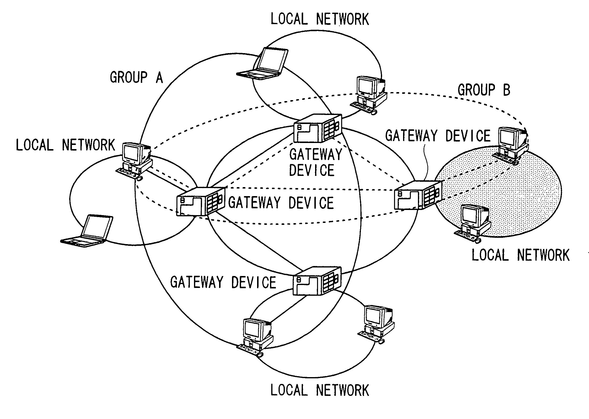
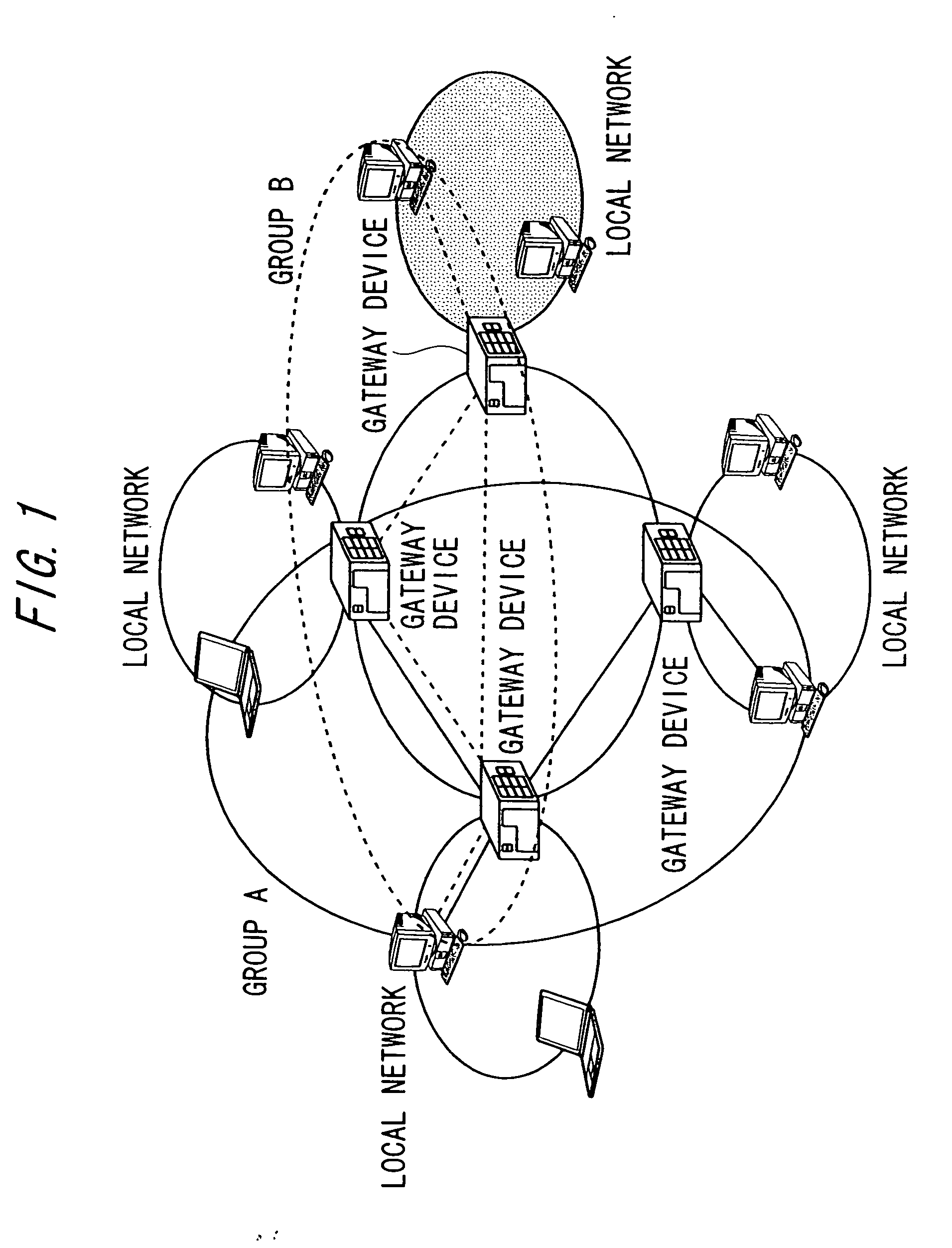
[0090]FIGS. 1 and 2 are diagrams for explaining a schematic configuration of the network system according to this embodiment.

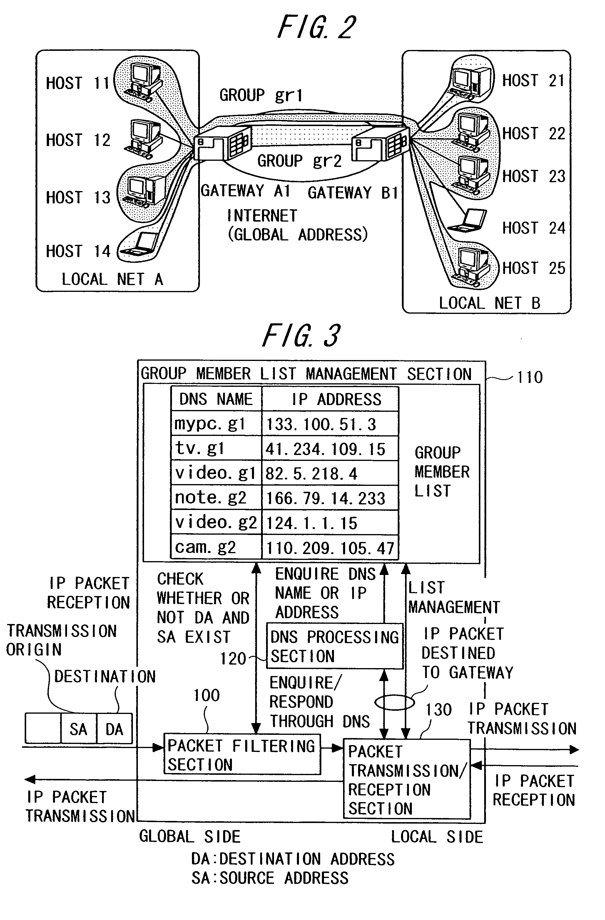
[0091] As shown in FIG. 2, the network system of the embodiment is composed of a local network A (hereinafter, referred to as “local net A”), a local network B (hereinafter, referred to as “local net B”), and the Internet. The local net A and local net B are each connected with hosts to be grouped (herein, hosts 11 to 14 and hosts 21 to 25, respectively). Note that the number of the hosts to be grouped can be appropriately set.

[0092] The hosts are each a terminal such as a household electrical appliance having a function of performing communications using IP packets. The hosts each have a global IP address to perform the communications by IP packets. Herein, IP addresses based on IPv4 are used. The local net A is connected to the Internet via a gateway A1. Similarly, the local net B is connected to the Interne...

second embodiment

(Second Embodiment)

[0130] Next, the drawings are referenced to describe a network system including a gateway (referred to also as “GW” or “gateway device”) according to a second embodiment of the present invention.

[0131] In the first embodiment, the IP address of each host needs to be a global address, which does not allow the use in an environment in which private IP addresses are often used in actuality. In addition, there is no other measure than to check a group name through a DNS as to whether a given host is a member of the group.

[0132] For example, if a given host belongs to two groups consisting of a group that provides a right to read a file and a group that allows a read / write right for full control, upon access from an unknown host, the given host must recognize a group through a DNS to find which right the unknown host has. In order to solve such a problem, the gateway device is additionally provided with the following new functions including:

[0133] a NAT (Network Add...

third embodiment

(Third Embodiment)

[0207] Next, the drawings are referenced to describe a network system including a gateway (referred to also as “GW” or “gateway device”) according to a third embodiment of the present invention.

[0208] In the above second embodiment, it is necessary for a network administrator to perform manual setting to establish a tunnel connection between gateways or create the global / local list. In this embodiment, description will be made of means for automating the setting with reference to the drawings. Herein, the description will be made of an example of using a protocol for transmitting / receiving the setting information between gateways, as such means. FIG. 11 is a sequence chart of the processing using the protocol.

[0209] Hereinafter, consideration will be made to the protocol for leading the gateway GW-B to create a group “g3” including the host “video” belonging to the gateway GW-B and a host called “PDA” belonging to a gateway GW-C.

[0210] 1. (Authentication Between...


PUM


Abstract

An IP packet relay apparatus provided between networks to relay an IP packet relating to a host belonging to a specific group, comprising: a list in which an IP address possessed by a host is associated with a group identifier for identifying a group to which the host belongs; a judgment unit judging whether an IP packet that has received from one network and is addressed to a host connected to another network is an IP packet relating to the same group or not with reference to the list; and a forwarding unit relaying an IP packet judged to be the IP packet relating to the same group.

Description

CROSS-REFERENCE TO RELATED APPLICATION [0001] This application is a continuation of International Application PCT / JP2003 / 011623, filed on Sep. 11, 2003, the contents of which are herein wholly incorporated by reference.BACKGROUND OF THE INVENTION [0002] 1. Field of the Invention [0003] The present invention relates to a technology of providing a closed network by grouping arbitrary hosts connected via a communication network in a virtual manner. [0004] 2. Description of the Related Art [0005] IP (Internet Protocol) networks have been coming into general use at a rapid pace. The IP networks are accordingly being connected with hosts other than personal computers (PCs) (for example, devices such as household electrical appliances capable of IP communications). The IP networks that are conventionally used mainly by high-functional personal computers (PCs) are being followed by ones that are used for controlling household electrical appliances or transmitting / receiving content between t...

Claims


Application Information

Patent Timeline
IPC IPC(8): H04L12/56H04L12/18
CPCH04L12/185H04L12/1886H04L45/04H04L12/4633H04L49/354H04L63/0272H04L61/5069
Inventor NOMURA, YUJIYAMANE, SHINJIUSHIKI, KAZUMASAKUROSE, YOSHITOSHIFUKAZAWA, MITSUNORI
Owner FUJITSU LTD
Why Eureka
Try Eureka