
Network tap/aggregator configured for power over ethernet operation

a technology of ethernet operation and network tap, applied in data switching networks, instruments, high-level techniques, etc., can solve problems such as the impedance of network operation

Active Publication Date: 2007-04-12
VIAVI SOLUTIONS INC
View PDF26 Cites 86 Cited by
  • Summary
  • Abstract
  • Description
  • Claims
  • Application Information

AI Technical Summary

Benefits of technology

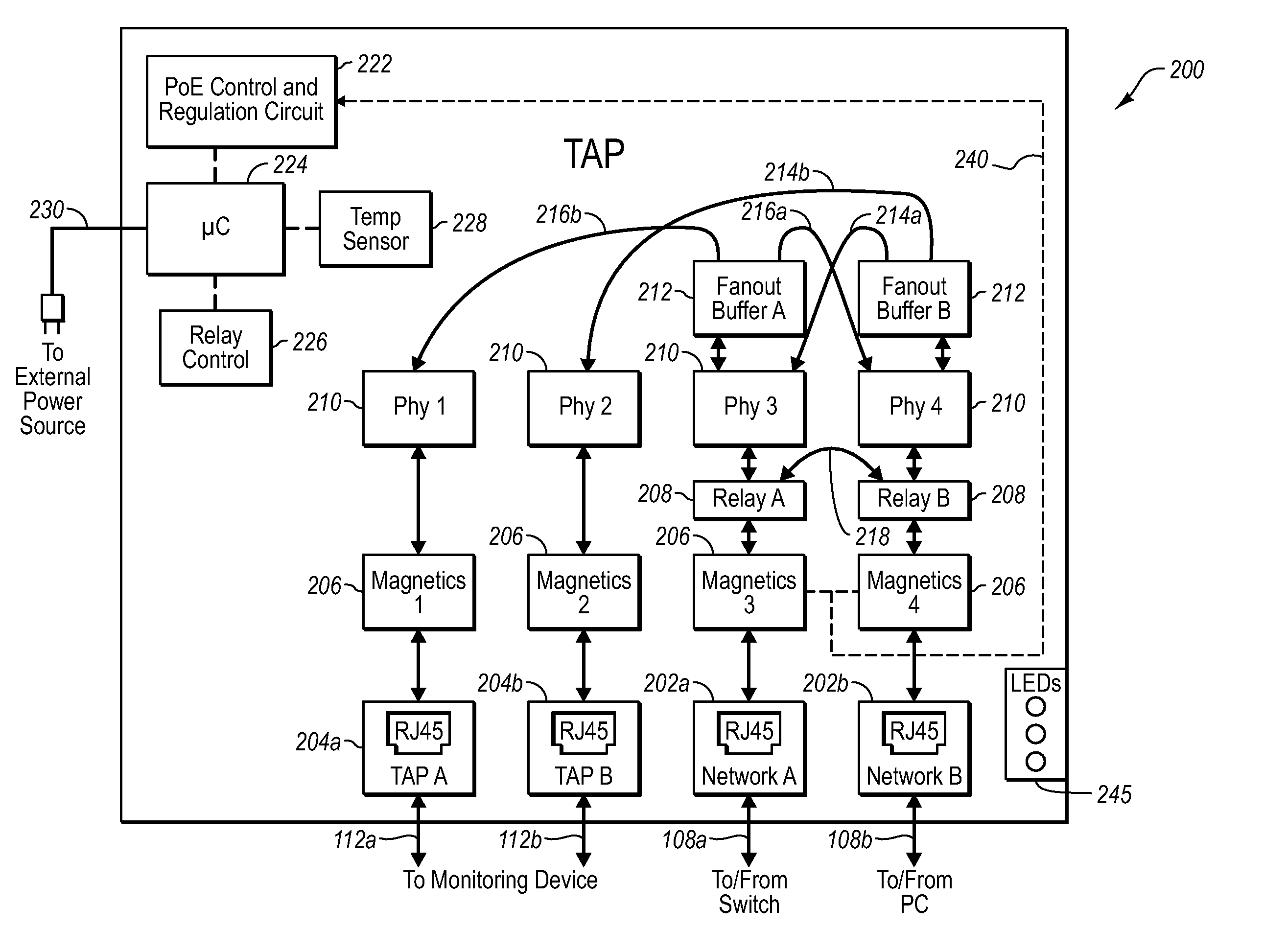
[0011] In one embodiment the network tap device array includes a plurality of network tap devices that are each powered by a POE supply. Powering of each network tap device in the array with a POE supply eliminates a potential network stream data failure point, such as when a traditional external power supply (e.g., converted AC power supply from a wall outlet) is used to power each tap. Interruption of this traditional external power supply during tap operation can interrupt the data stream passing through the tap, which as described above, can significantly impair operation of the network. Further, elimination of the power cord used to provide the traditional power supply to the network tap precludes the possibility of the power supply being interrupted as a result of a person tripping over the cord and unplugging the unit from the power outlet or from failure of the external power supply. Elimination of this failure point in turn contributes to a relative improvement in the reliability and operation of the network.
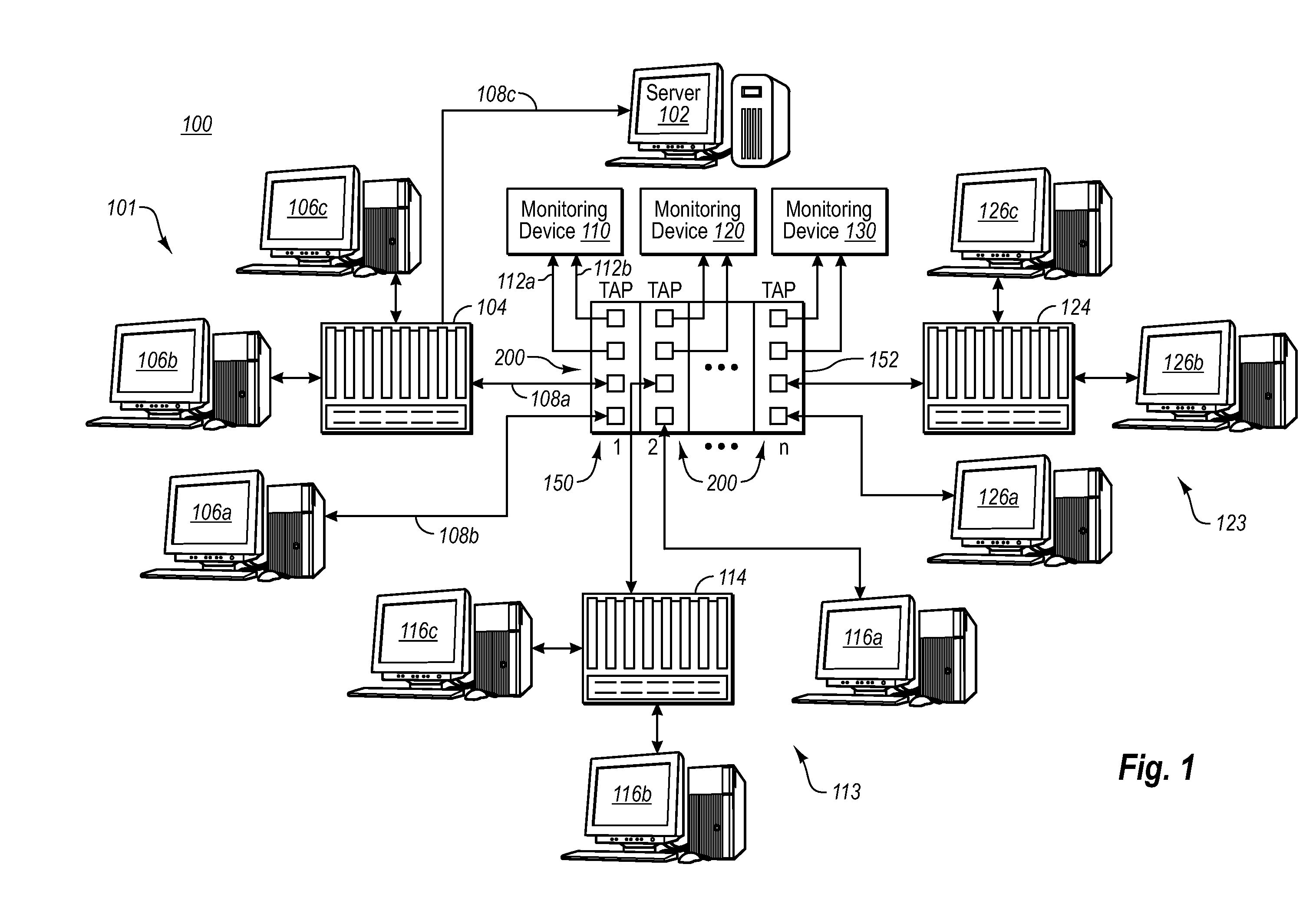
[0013] In another embodiment, a sub-chassis includes a plurality of network tap devices in the form of tap data cards. An aggregator card is also included in the sub-chassis. Each tap data card of the sub-chassis forwards a tapped data stream to the aggregator card. The aggregator card aggregates the data, then forwards the aggregated data to the monitoring device. The sub-chassis can be included in a larger chassis that is configured to receive multiple populated chassis, thereby offering the convenience of scale to tapping systems.

Problems solved by technology

Interruption of this traditional external power supply during tap operation can interrupt the data stream passing through the tap, which as described above, can significantly impair operation of the network.

Method used


Image

  • Network tap/aggregator configured for power over ethernet operation
  • Network tap/aggregator configured for power over ethernet operation
  • Network tap/aggregator configured for power over ethernet operation

Examples


Embodiment Construction

[0022] Reference will now be made to figures wherein like structures will be provided with like reference designations. It is understood that the drawings are diagrammatic and schematic representations of exemplary embodiments of the invention, and are not limiting of the present invention nor are they necessarily drawn to scale.

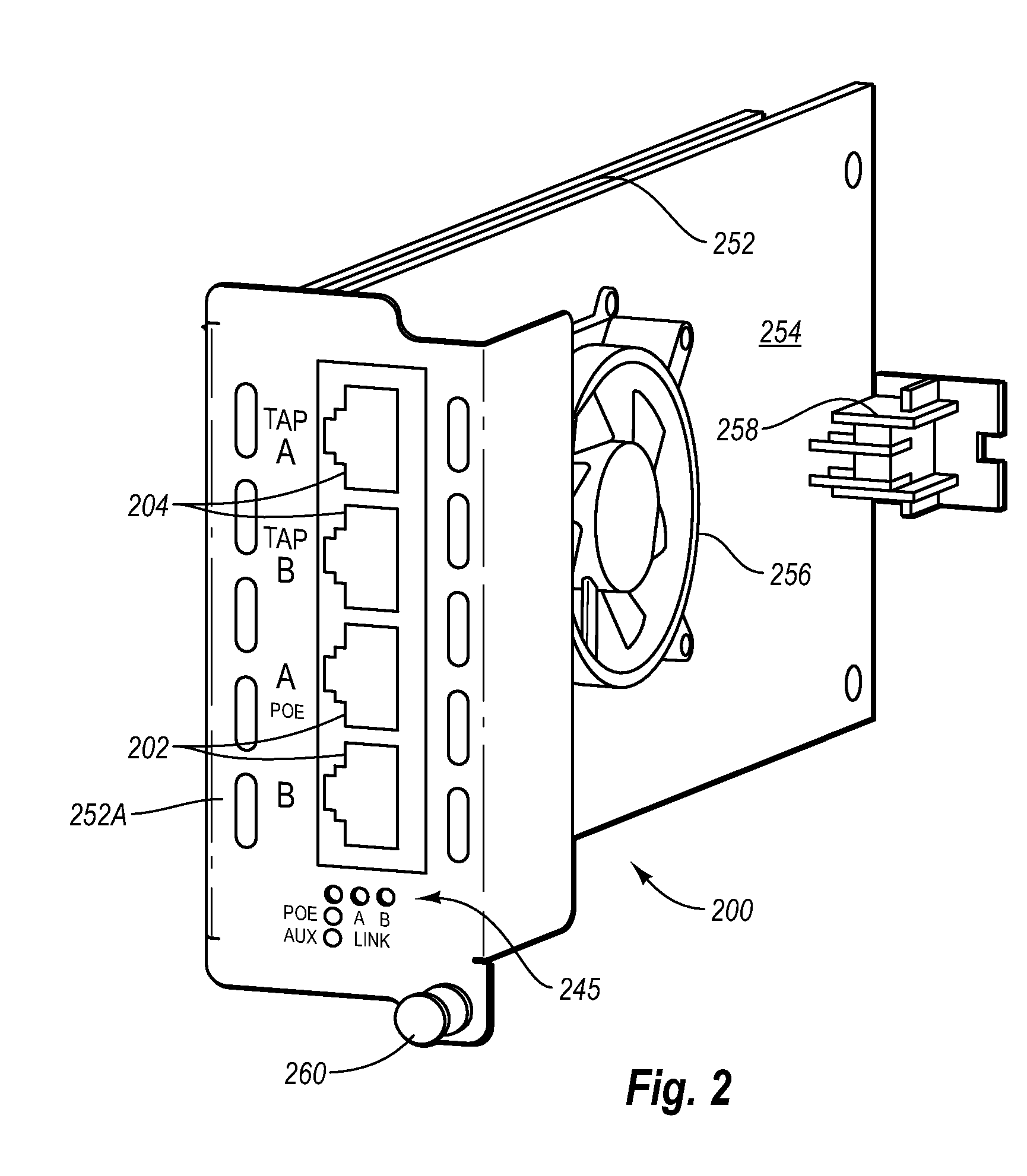
[0023]FIGS. 1-6 depict various features of embodiments of the present invention, which is generally directed to multi-port network tap / aggregators, taps, and associated devices, hardware and software, that are configured for Power Over Ethernet (“POE”) based operation in connection with copper-based Ethernet networks.

[0024] It should be noted that the disclosure concerning POE network tap systems, software, and devices that is included in commonly owned United States patent application entitled “Network Tap Device Powered by Power Over Ethernet,” filed concurrently herewith and incorporated herein in its entirety by this reference, is generally germane as ...


PUM


Abstract

A network tap device array capable of being powered by a power-over Ethernet (“POE”) supply is disclosed. The array enables data from multiple nodes in a communications network to be tapped and forwarded to a plurality of monitoring devices. In one embodiment the network tap device array includes a chassis that is configured to receive a plurality of network tap devices that are each powered by a POE supply. Each network tap device includes network ports for receiving and transmitting network data via communication cables and tap ports for forwarding the tapped network data to the monitoring device. In another embodiment, a sub-chassis includes a plurality of network tap devices and an aggregator that aggregates tapped data from each of the tap devices. The aggregator then forwards the aggregated data to the monitoring device. The sub-chassis can be included in a chassis that is configured to receive multiple populated chassis.

Description

CROSS-REFERENCE TO RELATED APPLICATIONS [0001] This application claims the benefit of U.S. Provisional Patent Application No. 60 / 735,262, filed Nov. 11, 2005, and entitled “NETWORK TAP / AGGREGATOR CONFIGURED FOR POWER OVER ETHERNET OPERATION;” and U.S. Provisional Patent Application No. 60 / 726,120, filed Oct. 12, 2005, and entitled “NETWORK TAP CONFIGURED FOR POWER OVER ETHERNET OPERATION,” both of which are incorporated herein by reference in their entireties.BACKGROUND [0002] 1. Technology Field [0003] The present invention generally relates to network tapping devices. In particular, the present invention relates to a network tap / aggregator and associated devices, hardware and software, that are configured for Power Over Ethernet (“POE”) based operation. [0004] 2. The Related Technology [0005] The dependence upon the use of data networks to transmit and receive data at high data rates has led to a corresponding interest in the ability to perform real-time monitoring and analysis of...

Claims


Application Information

Patent Timeline
Patent Type & Authority Applications(United States)
IPC IPC(8): H04L12/413
CPCH04L12/10H04L12/26H04L12/40032H04L12/40045H04L43/00Y02B60/33Y02D30/50
Inventor CICCHETTI, CHRISTOPHER J.LAWSON, ARTHUR M.LIGHT, GRETA L.GENTIEU, PAULBEYERS, TIMOTHY M.BLACKWELL, DONALD A.
Owner VIAVI SOLUTIONS INC
Learn More