Temporal and spatial shaping of multi-channel audio signals

a multi-channel audio and spatial shaping technology, applied in the field of multi-channel audio signal coding, can solve the problems of large room size, unnatural sounding transient signals, diffuse sound generated in the decoder, etc., and achieve the effect of improving the preservation of multi-channel signal spatial distribution

Active Publication Date: 2007-04-12
AVAGO TECH WIRELESS IP SINGAPORE PTE +2
View PDF11 Cites 62 Cited by
  • Summary
  • Abstract
  • Description
  • Claims
  • Application Information

AI Technical Summary

Benefits of technology

[0024] It is the object of the present invention to provide a concept for coding multi-channel audio signals that allows efficient coding providing an improved preservation of the multi-channel signals spatial distribution.

Problems solved by technology

Failing to do so will result in a perception of larger room size and unnatural sounding transient signals.
From a technical point of view, one of the key challenges in reconstructing multi-channel signals, as for example within a MPEG sound synthesis, consists in the proper re-production of multi-channel signals with a very wide sound image.
For transient signals, the diffuse sound generated in the decoder does not automatically match the fine temporal shape of the dry signals and does not fuse well perceptually with the dry signal.
This results in poor transient reproduction, in analogy to the “pre-echo problem” which is known from perceptual audio coding.
Due to the quite high time resolution of the MPEG Surround filter bank, TES processing requires only low-order filtering (1st order complex prediction) and is thus low in its computational complexity.
On the other hand, due to limitations e.g. related to temporal aliasing, it cannot provide the full extent of temporal control that the TP tool offers.
While this avoids the pre-echo type of unmasking, it cannot compensate for a second type of deficiency in the multi-channel output signal, which is due to the lack of spatial re-distribution:

Method used


Image

  • Temporal and spatial shaping of multi-channel audio signals
  • Temporal and spatial shaping of multi-channel audio signals
  • Temporal and spatial shaping of multi-channel audio signals

Examples


Embodiment Construction

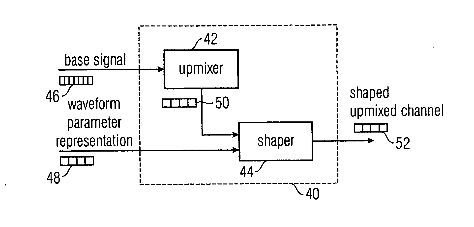
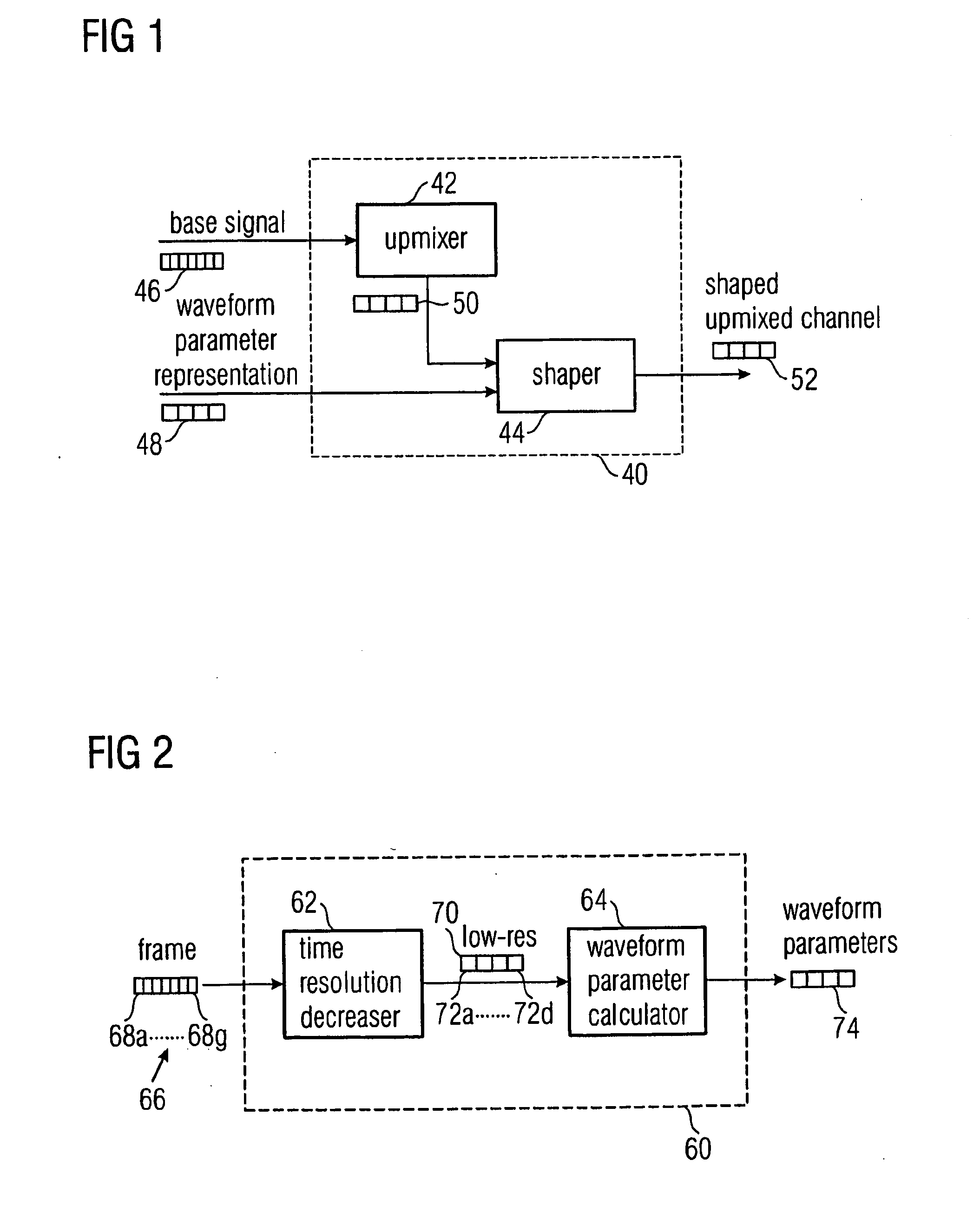
[0085]FIG. 1 shows an inventive decoder 40 having an upmixer 42 and a shaper 44.

[0086] The decoder 40 receives as an input a base signal 46 derived from an original multi-channel signal, the base signal having one or more channels, wherein the number of channels of the base signal is lower than the number of channels of the original multi-channel signal. The decoder 40 receives as second input a wave form parameter representation 48 representing a wave form of a low resolution representation of a selected original channel, wherein the wave form parameter representation 48 is including a sequence of wave form parameters having a time resolution that is lower than the time resolution of a sampling values that are organized in frames, the frames describing the base signal 46. The upmixer 42 is generating an upmix channel 50 from the base signal 46, wherein the upmix 50 is a low-resolution estimated representation of a selected original channel of the original multi-channel signal that...


PUM


Abstract

A selected channel of a multi-channel signal which is represented by frames composed from sampling values having a high time resolution can be encoded with higher quality when a wave form parameter representation representing a wave form of an intermediate resolution representation of the selected channel is derived, the wave form parameter representation including a sequence of intermediate wave form parameters having a time resolution lower than the high time resolution of the sampling values and higher than a time resolution defined by a frame repetition rate. The wave form parameter representation with the intermediate resolution can be used to shape a reconstructed channel to retrieve a channel having a signal envelope close to that one of the selected original channel. The time scale on which the shaping is performed is shorter than the time scale of a framewise processing, thus enhancing the quality of the reconstructed channel. On the other hand, the shaping time scale is larger than the time scale of the sampling values, significantly reducing the amount of data needed by the wave form parameter representation.

Description

FIELD OF THE INVENTION [0001] The present invention relates to coding of multi-channel audio signals and in particular to a concept to improve the spatial perception of a reconstructed multi-channel signal. BACKGROUND OF THE INVENTION AND PRIOR ART [0002] Recent development in audio coding has made available the ability to recreate a multi-channel representation of an audio signal based on a stereo (or mono) signal and corresponding control data. These methods differ substantially from older matrix based solutions such as Dolby Prologic, since additional control data is transmitted to control the re-creation, also referred to as up-mix, of the surround channels based on the transmitted mono or stereo channels. [0003] Hence, the parametric multi-channel audio decoders reconstruct N channels based on M transmitted channels, where N>M, and based on the additional control data. The additional control data represents a significant lower data rate than transmitting all N channels, maki...

Claims


Application Information

Patent Timeline
Patent Type & Authority Applications(United States)
IPC IPC(8): H04B14/04
CPCG10L19/008H04S3/008H03M7/30H04S3/00
Inventor DISCH, SASCHAHERRE, JUERGENNEUSINGER, MATTHIASBREEBAART, DIRK JEROENHOTHO, GERARD
Owner AVAGO TECH WIRELESS IP SINGAPORE PTE
Why Eureka
Try Eureka