
Four parts manhole enabling an easy install and height adjustment

a manhole and height adjustment technology, applied in the field of easy installation and height adjustable manholes, can solve the problem that no prior art teaches the concept of providing a height adjustable manhole system, and achieve the effect of convenient adjustment and easy installation

Inactive Publication Date: 2007-04-12
YOON JUNG HO
View PDF12 Cites 218 Cited by
  • Summary
  • Abstract
  • Description
  • Claims
  • Application Information

AI Technical Summary

Benefits of technology

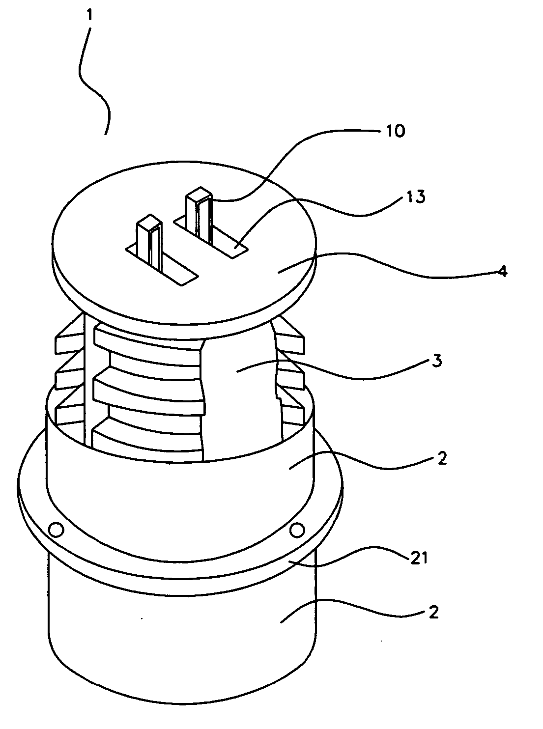
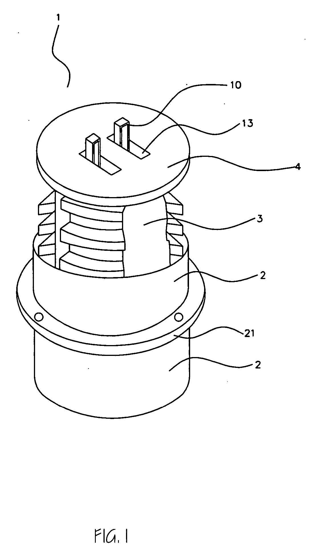
[0013] The manhole of current application is comprised of an outer-manhole pipe, an inner-manhole pie, a manhole cover, and a support pipe. Three concave arc band shape blades are horizontally located along the inner surface of the outer-manhole pipe in one layer. Five layers of concave arc shape blades, placed with same distance, are aligned to form three vertical columns of blades. Three convex arc band shape blades are horizontally located along the outer surface of the inner manhole pipe. Five layers of convex arc shape blades, placed with same distance, are aligned to form three vertical columns of blades. Size of all the arc band blades is the same. The size of the space between the two neighboring concave blades is the same as the size of a convex blade. When a space between the two neighboring concave blade is occupied by a convex blade, the inner-manhole pipe can move vertically freely. Once a desired vertical position of the inner-manhole pipe is reached, workers turn the inner-manhole pipe horizontally 60 degrees and put down the pipe. Then the concave and convex arc shape blades overlap each other. To separate the two pipes, lift up the inner-pipe slightly, turn 60 degrees horizontally and pull up the inner-pipe. The support pipe is engaged between the top flange of the inner-manhole pipe and top end of the outer manhole pipe to hold and support the distance between them. The structure of the manhole of current application enables an easy installation and easy adjustment of the height of the manhole cover from the basin structure of sewage treatment system.

Problems solved by technology

None of the prior art teaches to provide a height adjustable manhole system that enables an easy installation and height adjustment without utilizing screw threads system shown in the present application.

Method used


Image

  • Four parts manhole enabling an easy install and height adjustment
  • Four parts manhole enabling an easy install and height adjustment
  • Four parts manhole enabling an easy install and height adjustment

Examples


Embodiment Construction

[0024]FIG. 1 is a perspective view of a height adjustable manhole (1) of the current application. The manhole (1) is comprised of an outer-manhole pipe (2), an inner-manhole pipe (3), a manhole cover (4), and a support pipe (5).

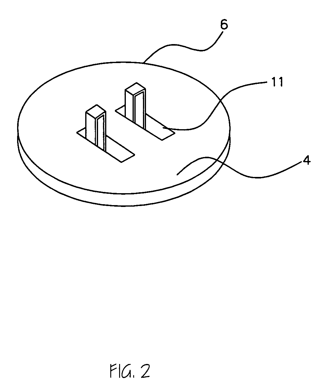
[0025]FIG. 2 is a perspective view of a manhole cover (4) with handle cam lock (6) for the height adjustable manhole (1) of the current application. FIG. 3 is a perspective view of a cam lock (6) of the manhole cover (4). FIG. 4 is a perspective view of an inner- manhole pipe (3) equipped with a flange (7). The flange (7) has an opening (8) to receive cam shaft (9). When the handle (10) of the cam lock (6) is vertically upward, the cam shaft (9) is placed in down part of the cylindrical cam hole (11) due to the shape of cam (12). When the handle (10) of the cam lock (6) is laid down and inserted into the cam lock box (13), the camshaft (9) is placed in the upper part of the cam hole (11).

[0026] To close the manhole cover (4), a worker picks up the handle (1...


PUM


Abstract

A manhole comprised of four parts is provided. The manhole is comprised of an outer-manhole pipe, an inner-manhole pipe, a manhole cover, and a support pipe. Pluralities of concave arc band shape blades are horizontally developed along the inner surface of the outer manhole pipe. Same number of convex arc band shape blades is horizontally developed along the outer surface of the inner manhole pipe. The inner-manhole pipe is inserted into the outer-manhole pipe vertically when the two kinds of arc shape blades aligned to make pass way for each other. When a desired height is reached, workers rotate the inner-manhole pipe 60 degrees horizontally and put down the inner-manhole pipe. Then the two kinds of blades are overlapped and fix the height of the manhole cover. A support pipe, comprised of two pieces of equal hemi-pipe connected one end, is engaged between the top flange of the inner-manhole pipe and top end of the outer manhole pipe to hold and support the distance between them.

Description

FIELD OF INVENTION [0001] Current application is related with a road installing manhole, especially related with an easy installation and height adjustable manhole comprised of four parts. BACKGROUND OF THE INVENTION [0002] Most of manhole is comprised of one main steel pipe and one cover. Once the manhole is installed on the street over sewage line and many other facilities for city life, the position of the manhole cover from the base of the pavement or from the outer surface of the huge construction of a sewage line is fixed. However, due to the severe weather conditions such as extreme temperature change and rains, there develop creeks between the manholes and the road surface surrounding them. Those creeks are not only very dangerous for cars and pedestrians passing by the area. Most local authorities spend lots of their budget to cover up those creeks. The best way is to pave the whole road of that area and paint the lines. But, as the pavements are repeated, the surface of th...

Claims


Application Information

Patent Timeline
IPC IPC(8): E02D29/14
CPCE02D29/124E02D29/14
Inventor YOON, JUNG HO
Owner YOON JUNG HO
Learn More