Wireless communication over a transducer device

a transducer and wireless technology, applied in the direction of cordless telephones, near-field systems using receivers, modulation, etc., can solve the problems of prohibitive relative size and weight of individual antennas for transmitting and receiving, and achieve the reduction of the overall size of the wireless transceiver device, the size and weight of the power source for powering the corresponding wireless device, and the effect of increasing portability

Inactive Publication Date: 2007-04-12
FREELINC HLDG LLC
View PDF50 Cites 148 Cited by
  • Summary
  • Abstract
  • Description
  • Claims
  • Application Information

AI Technical Summary

Benefits of technology

[0004] Recent advancements in integrated circuit technology render it possible to reduce an overall size of wireless transceiver devices. Additionally, the size and weight of power sources for powering corresponding wireless devices has been reduced to support increased portability. That is, wireless transceiver devices are now smaller than ever before. As a result, a relative size and weight associated with the use of individual antennas for transmitting and receiving can be prohibitive due to space restrictions in certain wireless applications.
[0005] It would be an advancement in the art to reduce the power, cost, size and weight of a transceiver system such as a transducer and related circuitry for transmitting and receiving wireless signals based on inductive coupling.

Problems solved by technology

As a result, a relative size and weight associated with the use of individual antennas for transmitting and receiving can be prohibitive due to space restrictions in certain wireless applications.

Method used


Image

  • Wireless communication over a transducer device
  • Wireless communication over a transducer device
  • Wireless communication over a transducer device

Examples


Embodiment Construction

[0076] A description of preferred embodiments of the invention follows.

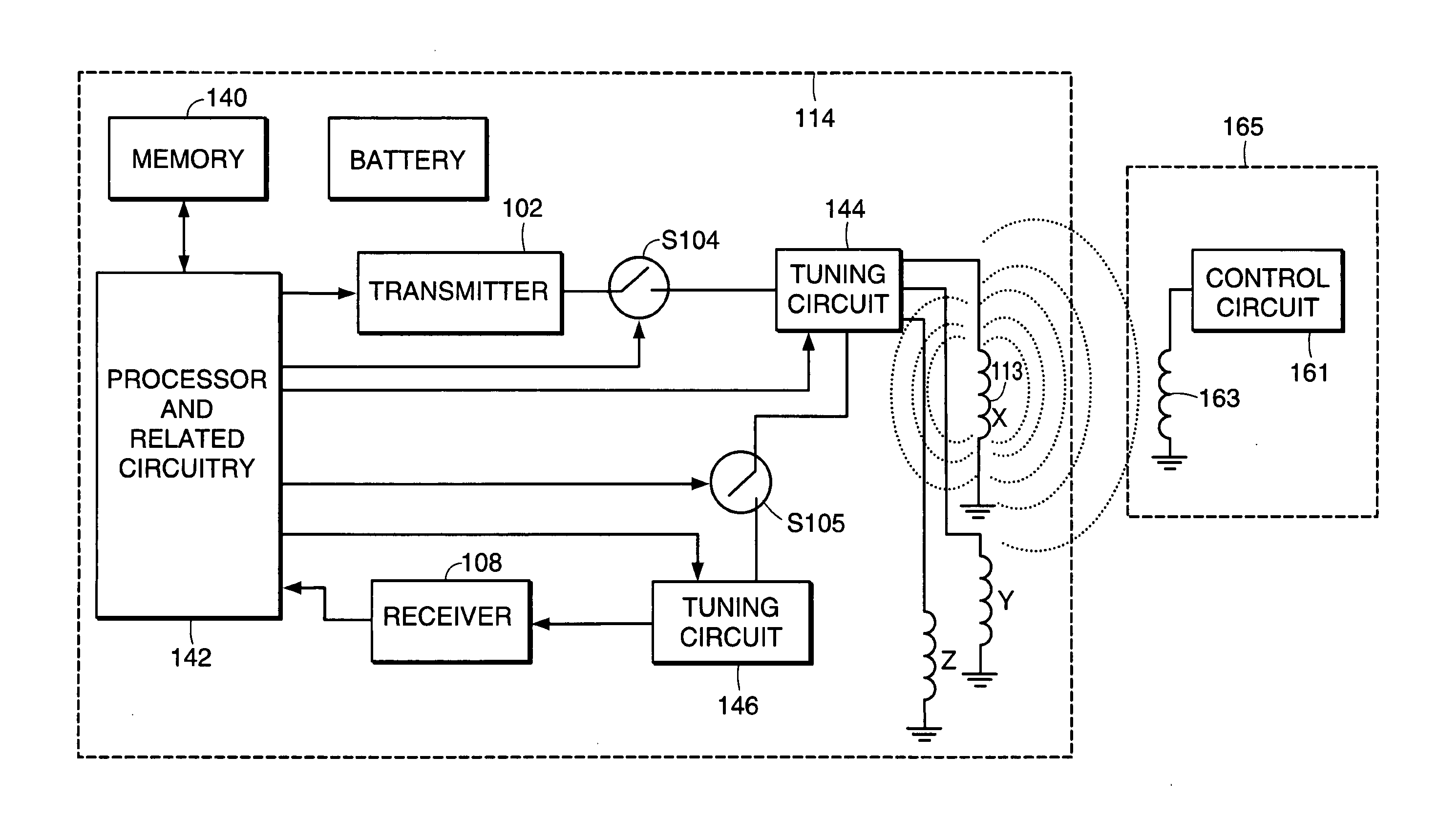
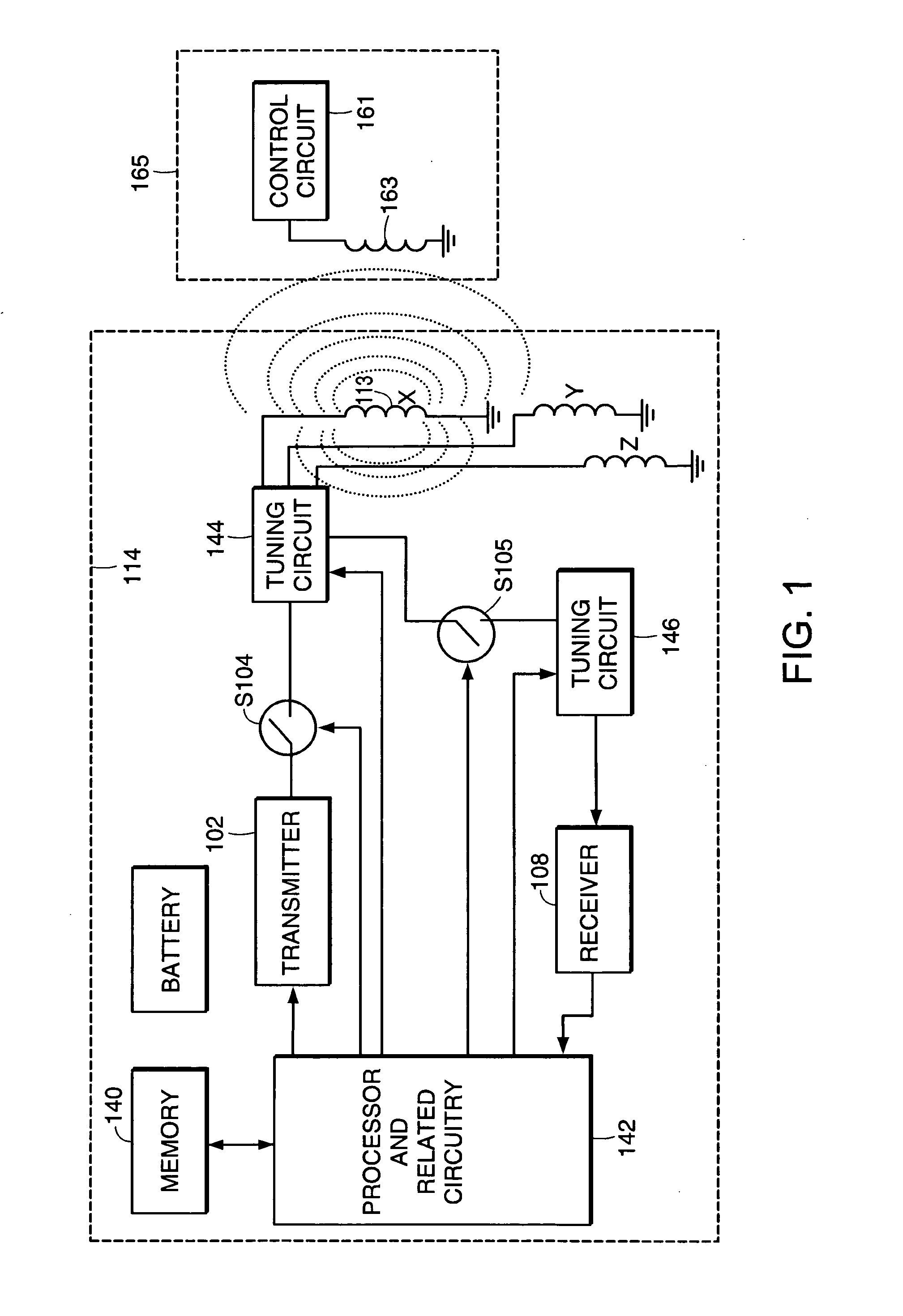
[0077]FIG. 1 is a block diagram illustrating a transceiver system according to certain principles of the present invention. As shown, a first transceiver 114 is coupled via an inductive or magnetic field to second transceiver 165. First transceiver 114 is optionally portable so that its orientation is not fixed with respect to second transceiver 165, which includes control circuit 161 and transducer 163. Second transceiver 165 itself can be portable while first transceiver is a fixed. Further, first transceiver 114 and second transceiver 165 both can be portable so that they are mobile and oriented in any manner with respect to each other.

[0078] Additional details of transceiver devices and methods of communicating are discussed in pending U.S. application Ser. No. 09 / 053,107 filed on Apr. 1, 1998, the entire teachings of which are incorporated herein by this reference.

[0079] Generally, tuning circuit 144 and ...


PUM


Abstract

One aspect of the present invention is generally directed towards a system and method of tuning a transducer for transmitting and receiving a wireless signal. In an illustrative embodiment, a single transducer is coupled to a first or second circuit for either transmitting or receiving, respectively. Generally, electrical characteristics of the first circuit are adjusted to increase a magnetic field generated by the transducer. Conversely, electrical characteristics of the second circuit are adjusted to increase a signal generated by the transducer for receiving a magnetic field. Accordingly, a single transducer device can be tuned for either transmitting or receiving a corresponding wireless signal.

Description

RELATED APPLICATIONS [0001] This application is a Continuation of U.S. application Ser. No. 10 / 004,989, filed on Dec. 3, 2001, which is a Continuation-in-part of U.S. application Ser. No. 09 / 942,372, filed on Aug. 29, 2001, now abandoned, which claims the benefit of U.S. Provisional Application No. 60 / 296,229, filed on Jun. 6, 2001 and U.S. Provisional Application No. 60 / 276,398, filed on Mar. 16, 2001. The entire teachings of the above applications are incorporated herein by reference.BACKGROUND OF THE INVENTION [0002] Inductive antenna devices have been incorporated in transceivers to transmit and receive wireless signals for quite some time. In a typical application, a transceiver device supporting bi-directional communication includes two specifically tuned antennas, one of which is tuned for transmitting while the other is tuned for receiving. [0003] Unlike RF (Radio Frequency) antennas, inductive antennas are often independently tuned for more efficiently transmitting or recei...

Claims


Application Information

Patent Timeline
Patent Type & Authority Applications(United States)
IPC IPC(8): H04B5/00H04B5/02H04B5/06H04M1/60H04M1/727H04M1/737
CPCH04B5/0012H04B5/0081H04B5/02H04M1/6041H04M1/6066H04M1/727H04M1/737H04R2420/07
Inventor TERRANOVA, DOMENIC F.PALERMO, VINCENT
Owner FREELINC HLDG LLC
Why Eureka
Try Eureka