
Various methods and apparatuses for estimating characteristics of an electronic system's design

a technology of electronic systems and characteristics, applied in the direction of cad circuit design, program control, instruments, etc., can solve the problems of not being physically possible to connect, requiring revisions to the original design and simulation stages, and not being able to notice problems

Active Publication Date: 2007-04-12
META PLATFORMS TECH LLC
View PDF19 Cites 22 Cited by
  • Summary
  • Abstract
  • Description
  • Claims
  • Application Information

AI Technical Summary

Benefits of technology

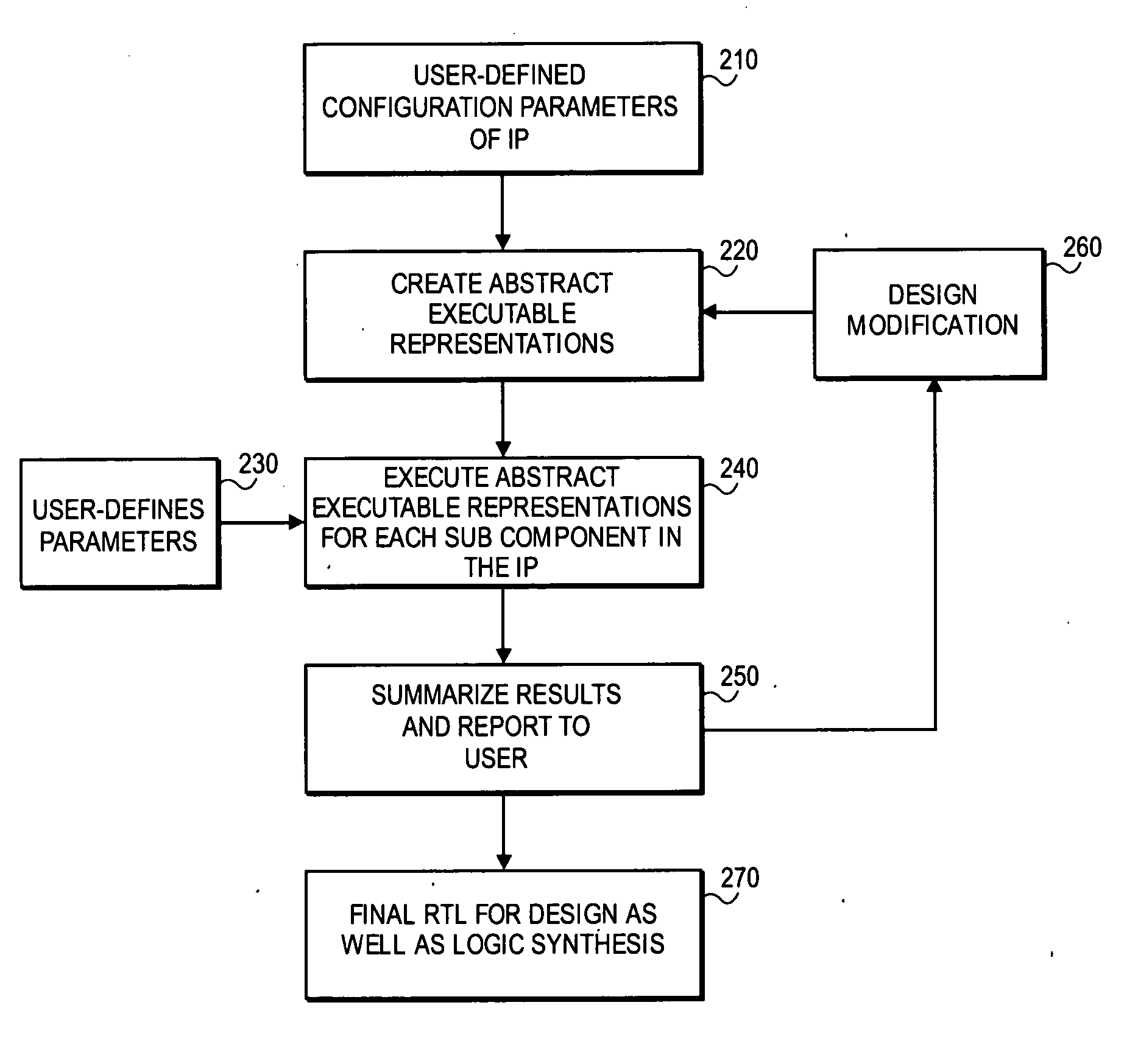
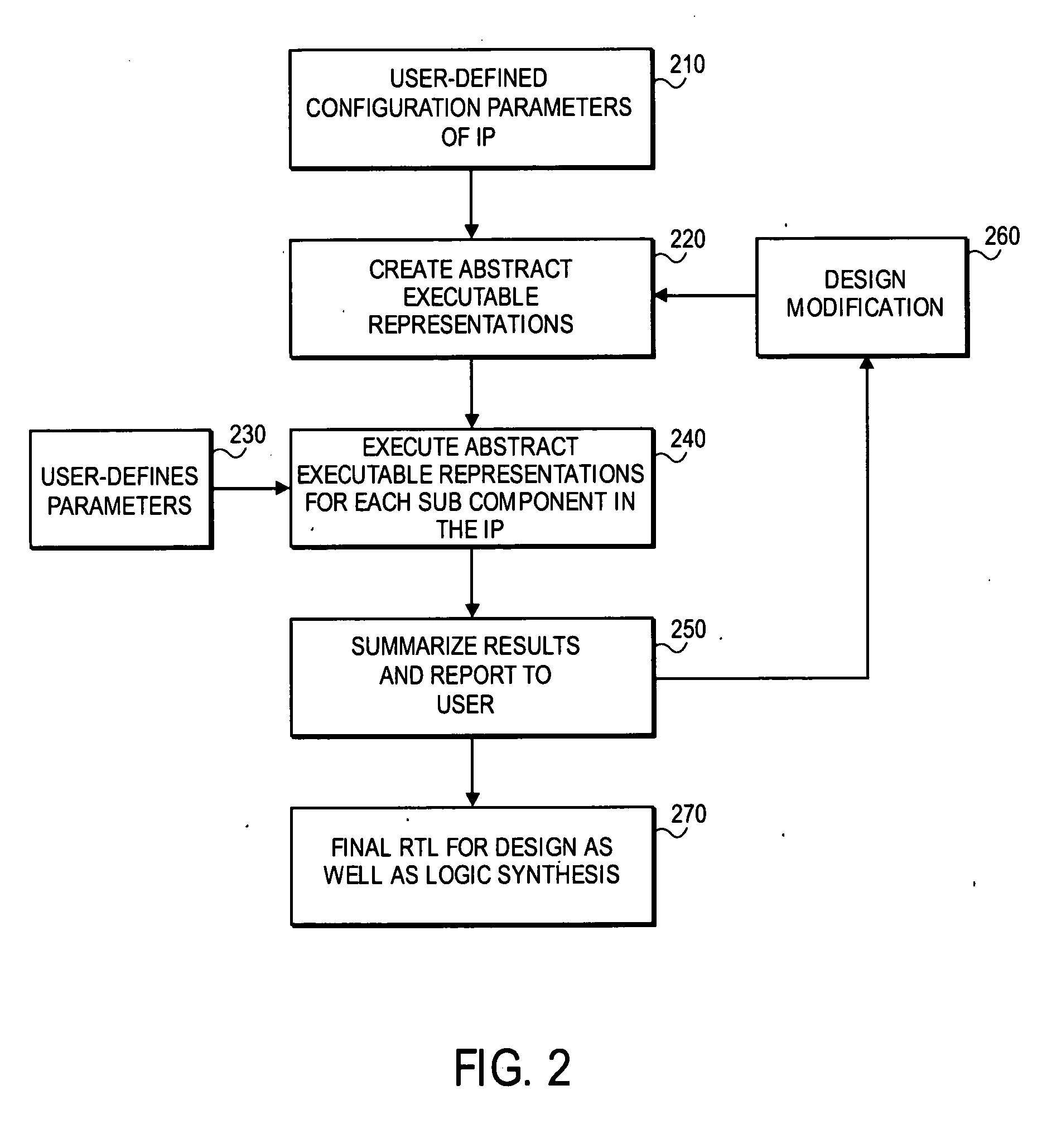
[0004] Methods and apparatuses are described for an Intellectual Property (IP) Generator for estimating timing, area, and power characteristics of an electronic system design. The IP Generator receives a user-supplied file having data describing a configuration of an IP design having multiple levels of hierarchy. The data includes one or more configuration parameters. The IP Generator also receives user-supplied technology parameters and data-flow information. The IP generator creates an abstract executable representation for each IP sub component making up the IP core design. Abstract executable representations of Timing, Area, and Power (TAP) characteristics for each IP sub component in the IP design execute to allow the corresponding TAP modules in the IP generator to estimate timing, area, and power quantities of a predicted gate-level circuit design. The IP generator correlates estimated amount and types of circuit level components that make up each IP sub component based on the user supplied one or more configuration parameters. The IP generator may translate those estimates to quantities by applying the technology parameters or data flow activity parameters. The IP generator reports the predicted timing, area, or power results to the user via a graphic user interface. The IP generator provides the predicted timing, area, or power results to the user prior to logic synthesis of a Register Transfer Level (RTL) design of the IP block.

Problems solved by technology

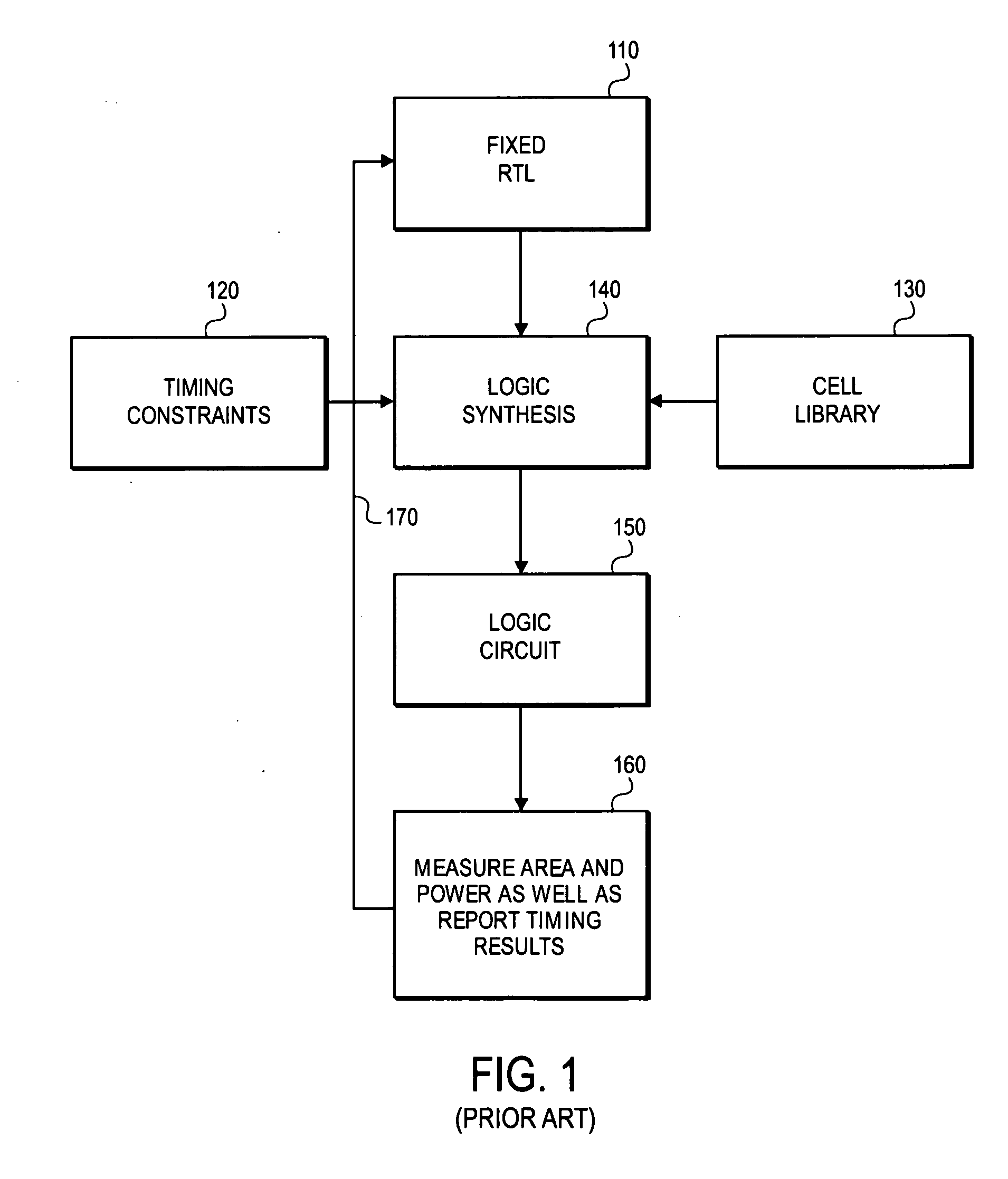
Such an approach can potentially require revisions to the original design and simulation stages if it is not physically possible to place the components in such a way as to properly represent the original design.
For example, a System on a Chip design may require the placement of components in such a way that is not physically possible to connect the various IP blocks in the manner when the architectural design was generated for this System on a Chip.
Under the traditional approach, such a problem may not be noticed until after the design and simulation stages have completed.

Method used


Image

  • Various methods and apparatuses for estimating characteristics of an electronic system's design
  • Various methods and apparatuses for estimating characteristics of an electronic system's design
  • Various methods and apparatuses for estimating characteristics of an electronic system's design

Examples


Embodiment Construction

[0015] In the following description, numerous specific details are set forth, such as examples of specific protocol commands, named components, connections, types of modules, etc., in order to provide a thorough understanding of the present invention. It will be apparent, however, to one skilled in the art that the present invention may be practiced without these specific details. In other instances, well known components or methods have not been described in detail but rather in a block diagram in order to avoid unnecessarily obscuring the present invention. Thus, the specific details set forth are merely exemplary. The specific details may be varied from and still be contemplated to be within the spirit and scope of the present invention.

[0016] In a highly configurable System on a Chip (SOC) interconnect, many configuration options enable a user to make trade-offs between Timing (latency and frequency), Area (logic gate / transistor and wire routing), and Power (dynamic and static)...


PUM


Abstract

Methods and apparatuses are described for an Intellectual Property (IP) Generator for estimating timing, area, and power characteristics of an electronic system design. The IP Generator receives a user-supplied file having data describing a configuration of an IP design having multiple levels of hierarchy. The IP Generator also receives user-supplied technology parameters and data-flow information. The IP generator correlates estimated timing, area, and power characteristics for each IP sub component based on the user supplied technology parameters, data-flow information and configuration parameters. The IP generator reports the timing, area, and power estimates to a user via a graphic user interface prior to a transformation of a Register Transfer Level (RTL) design into the gate-level circuit design.

Description

RELATED APPLICATION [0001] This application is a continuation-in-part application and claims the benefit of U.S. patent application Ser. No. 11 / 246,809, entitled “METHOD AND APPARATUS FOR AN EXECUTABLE PARAMETERIZED TIMING MODEL,” filed on Oct. 7, 2005.FIELD OF THE INVENTION [0002] Aspects of embodiments described herein apply to the development process of electronic systems, especially System on a Chip (SOC). BACKGROUND [0003] In computer networks, internetworking, communications, integrated circuits, etc., where there is a need to communicate information, there may be interconnections established to facilitate the transfer of the information. Interconnects may provide the physical communication network between two agents such as agents of Intellectual Property (IP) blocks. When designing systems that comprise such IP blocks and interconnects, the physical layout of IP blocks and its corresponding interconnects typically occur after the design / architecture and simulation stages are...

Claims


Application Information

Patent Timeline
Patent Type & Authority Applications(United States)
IPC IPC(8): G06F17/50G06F9/45
CPCG06F17/5045G06F2217/78G06F2217/84G06F30/30G06F2119/06G06F2119/12
Inventor HAMILTON, STEPHENSWARBRICK, IAN ANDREWEVANS, SCOTT CARLTONWEBER, WOLF-DIETRICHTOMLINSON, JAY S.
Owner META PLATFORMS TECH LLC
Learn More