Freeze protection for on-board vehicle emissions treatment system

a technology for emissions treatment and on-board vehicles, which is applied in the direction of machines/engines, liquid handling, packaging goods types, etc., to achieve the effects of reducing the possibility of freezing, avoiding unnecessary heating of primary fuel, and reducing the potential for components

Inactive Publication Date: 2007-04-19
FORD GLOBAL TECH LLC
View PDF27 Cites 19 Cited by
  • Summary
  • Abstract
  • Description
  • Claims
  • Application Information

AI Technical Summary

Benefits of technology

[0026] As such, the present invention reduces the potential for freezing of components in a secondary fluid storage and distribution system by moving the secondary fluid, which may be used as an emissions treatment substance, away from the co-located filling area after filling. For applications using co-fueling of a primary fuel and urea, the invention prevents formation of urea ice on the spring side of a check valve disposed near the terminal end of the urea fill tube, which would otherwise prevent the check valve from opening and filling of the emissions treatment system.
[0027] The present invention does not require heating of the emissions treatment substance to reduce the possibility of freezing of fill-related components, such as a valve. However, for applications that include heating of the emissions treatment substance, the present invention moves the emissions treatment substance away from the primary fuel / vapor area to an area where it can be passively or actively heated to further reduce the possibility of freezing while avoiding unnecessary heating of the primary fuel.

Problems solved by technology

However, due to the combustibility of the primary fuel and / or fuel vapor, these approaches may be problematic in applications where the emissions treatment system and primary fuel supply share a common space.

Method used


Image

  • Freeze protection for on-board vehicle emissions treatment system
  • Freeze protection for on-board vehicle emissions treatment system
  • Freeze protection for on-board vehicle emissions treatment system

Examples


Embodiment Construction

)

[0012] As those of ordinary skill in the art will understand, various features of the present invention as illustrated and described with reference to any one of the Figures may be combined with features illustrated in one or more other Figures to produce embodiments of the present invention that are not explicitly illustrated or described. The combinations of features illustrated provide representative embodiments for typical applications. However, various combinations and modifications of the features consistent with the teachings of the present invention may be desired for particular applications or implementations.

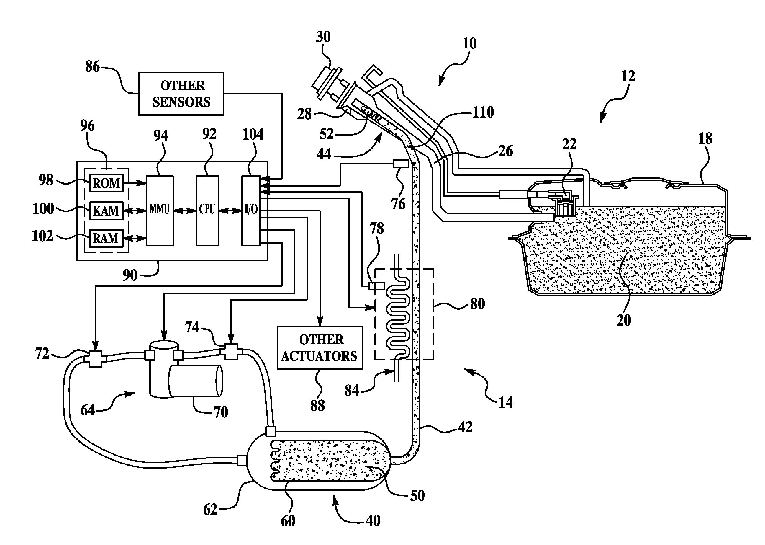
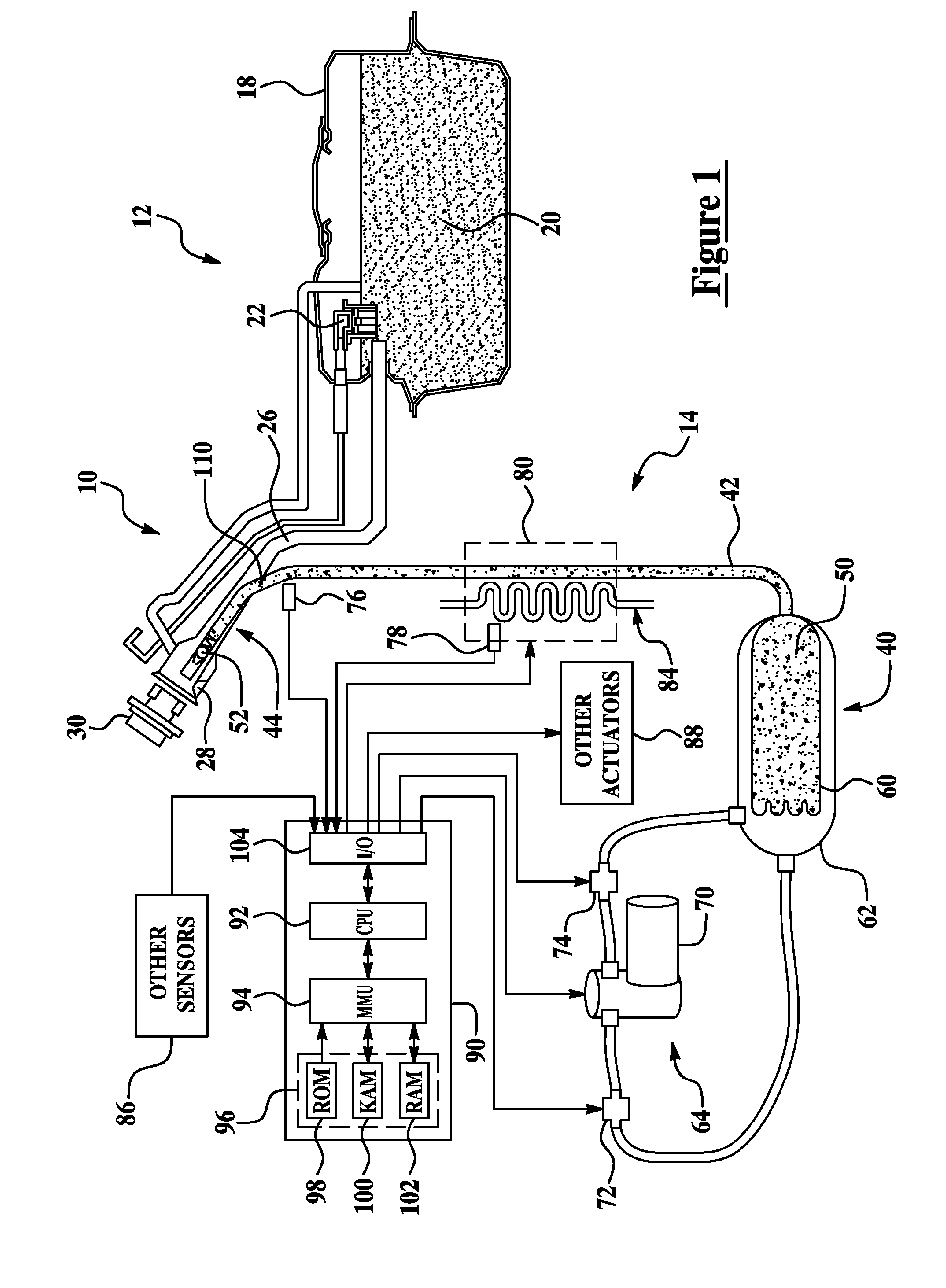
[0013] Referring now to FIG. 1, a block diagram illustrating one embodiment of a system or method for controlling an on-board vehicle emissions treatment system according to the present invention is shown. System 10 includes a primary fluid storage and distribution system 12 and a secondary fluid storage and distribution system 14 that are mounted on a vehicle (not s...


PUM

PropertyMeasurementUnit
pressureaaaaaaaaaa
physical propertiesaaaaaaaaaa
freezing susceptibilityaaaaaaaaaa

Abstract

Freeze protection of an on-board emissions treatment substance storage and distribution system in a vehicle includes moving the emissions treatment substance away from a primary fuel/vapor area after filling of the emissions treatment system. In one embodiment an on-board emissions treatment system has a fill tube with a portion extending into a primary fuel fill pipe to facilitate co-fueling of the primary fuel and emissions treatment substance. A pressure differential or vacuum is created in the emissions treatment fill tube after filling to move the emissions treatment substance away from a check valve disposed at the terminal end of the fill tube to prevent freezing of the check valve after filling. The emissions treatment substance may be moved out of the co-located portion of the fill tube to an area where passive or active heating of the fill tube may be applied.

Description

BACKGROUND OF THE INVENTION [0001] 1. Field of the Invention [0002] The present invention relates to systems and methods for controlling an on-board emissions treatment system of a vehicle. [0003] 2. Background Art [0004] Manufacturers of vehicles and internal combustion engines used in a variety of diverse applications are continually striving to improve engine / vehicle fuel economy and performance while reducing emissions. Effective emission control strategies often include control of the combustion event in addition to various devices that treat the exhaust before it reaches the atmosphere. Various types of emission control systems introduce one or more substances directly or indirectly to the engine via the fuel supply, air / fuel intake, exhaust, or directly to an engine cylinder or emissions control device, such as a catalyst. For example, substances acting as reducing agents or reductants, such as aqueous urea or hydrocarbons (other than fuel) may be used in lean air / fuel ratio ...

Claims


Application Information

Patent Timeline
Patent Type & Authority Applications(United States)
IPC IPC(8): F01N3/00F01N3/10
CPCB60K15/04B60K2015/0319B60K2015/03348F01N3/2066F01N3/208F01N2610/02F01N2610/03F01N2610/10F01N2610/14F01N2610/1413F01N2610/1466F01N2900/1808F01N2900/1811F01N2900/1812F02M37/0076Y02T10/24Y02T10/12Y10T137/1189Y10T137/6416Y02A50/20
Inventor LEVIN, MICHAEL
Owner FORD GLOBAL TECH LLC
Why Eureka
Try Eureka