Structure for installing protection member and working machine including the same
- Summary
- Abstract
- Description
- Claims
- Application Information
AI Technical Summary
Benefits of technology
Problems solved by technology
Method used
Image

Examples
first embodiment
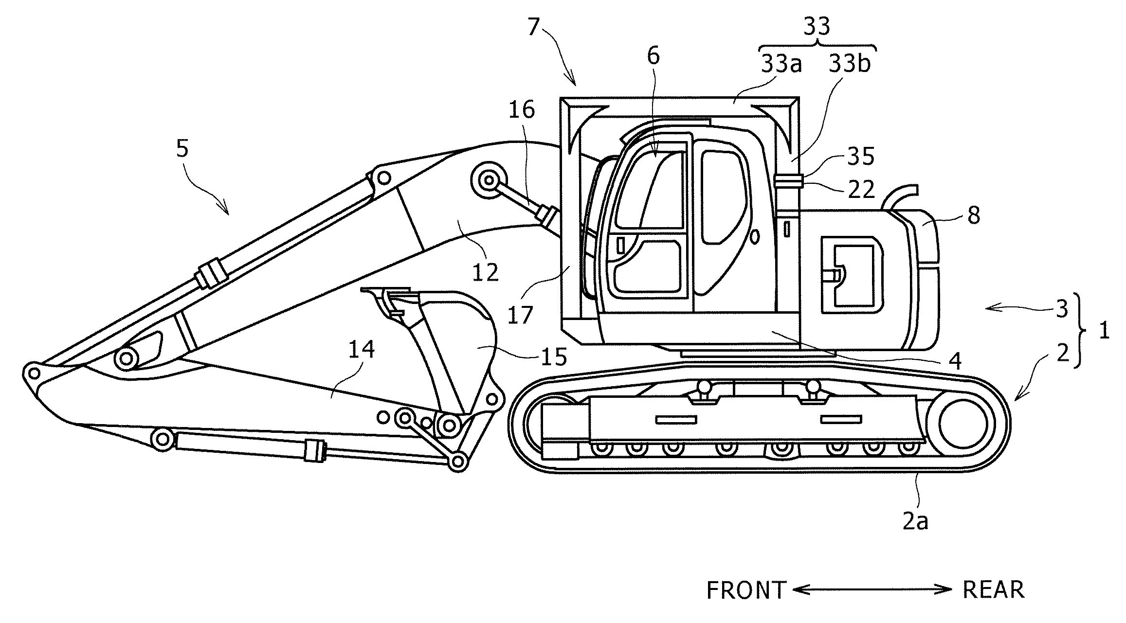
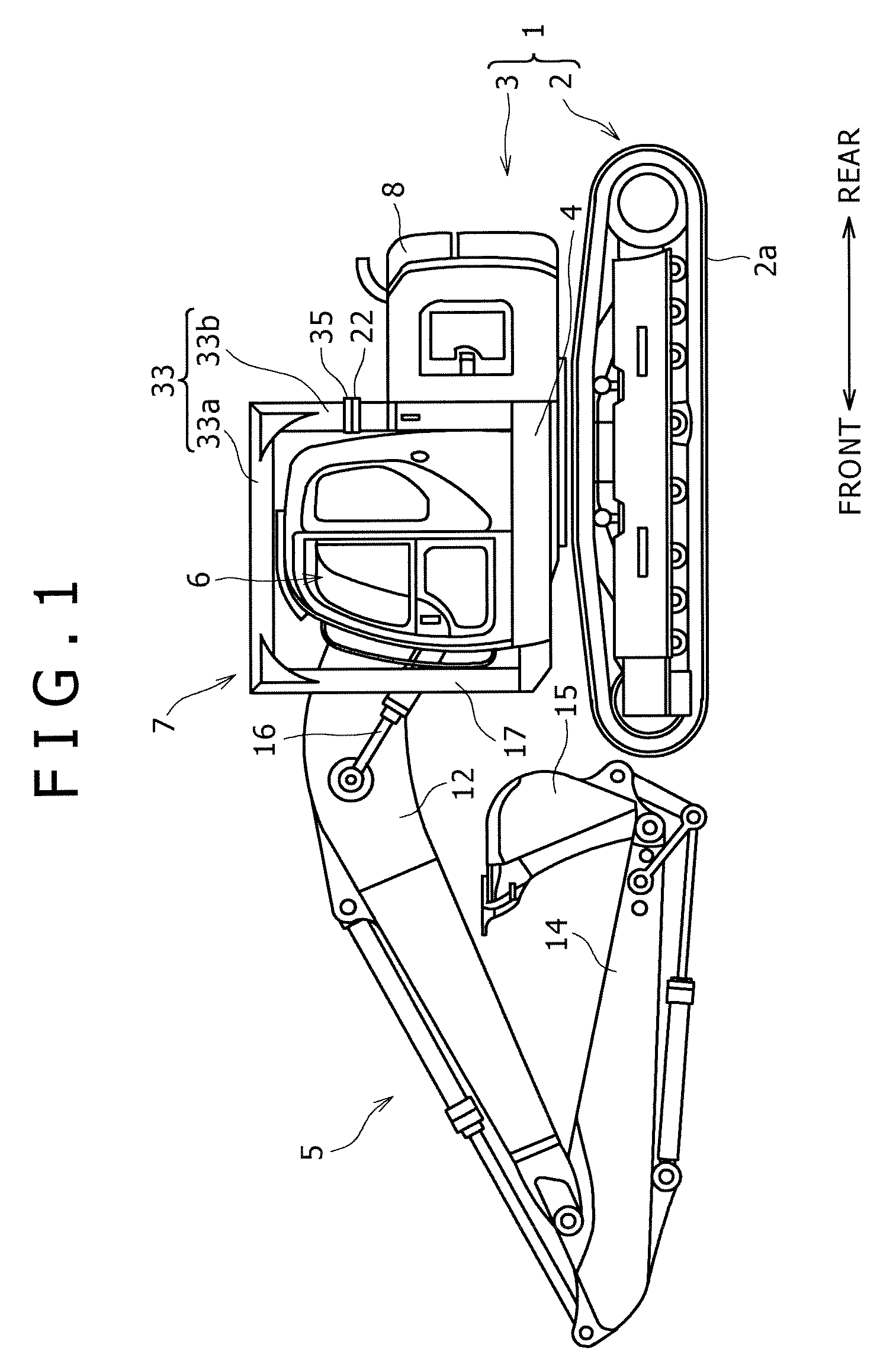
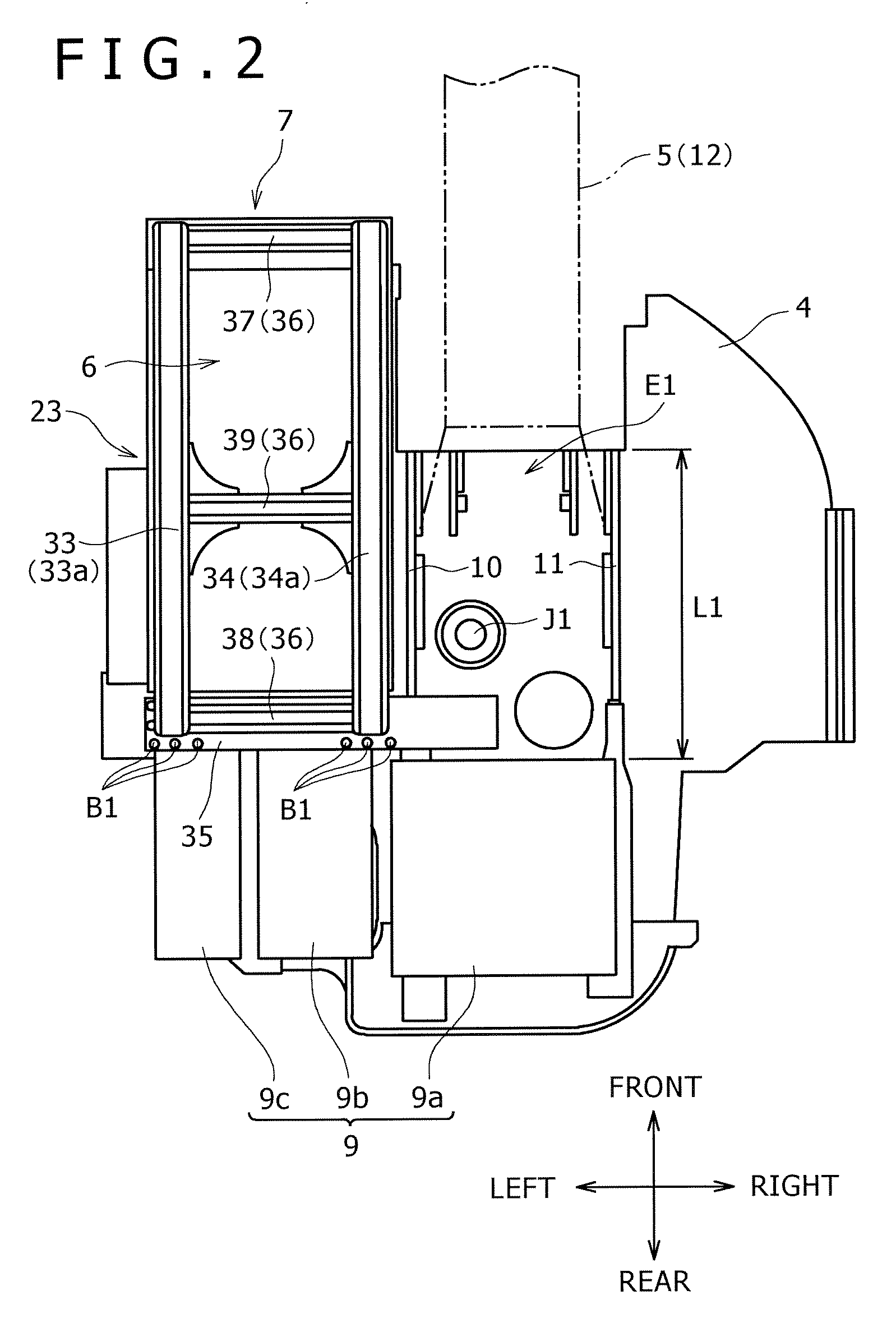
[0040]FIG. 1 is a side view showing the overall configuration of a hydraulic excavator according to the present invention; FIG. 2 is a partially simplified plan view showing the rotating frame of the upper rotating body shown in FIG. 1; FIG. 3 is a partially simplified back view of the upper rotating body shown in FIG. 2; and FIG. 4 is a cross-sectional view along the line IV-IV in FIG. 3.
[0041] Referring now to these figures, the hydraulic excavator 1 as an example of a working machine includes a lower traveling body 2 provided with a crawler 2a and an upper rotating body 3 mounted on the lower traveling body 2.
[0042] The upper rotating body 3 includes a rotating frame (placing frame) 4 attached around a vertically extending rotating axis J1 rotatably with respect to the lower traveling body 2. In the front part of the rotating frame 4, an attachment area E1 (indicated by the width W1 and the length L1) for attaching an attachment 5 therein is set in approximately the center in th...
second embodiment
[0072] In the second embodiment, the lateral frame 43 for connecting the upper end portions of the rear supports 40 to 42 is connected directly to the cover parts 33a and 34a. That is, it is possible to omit the flexion parts 33b and 34b, fixing plate 35, and second connecting bar 38 in the above-described embodiment.
[0073] Also in this second embodiment, as shown in FIG. 7B, the cover parts 33a and 34a are arranged at positions shifted leftward from the area E2 where the attachment 5 is raised and lowered. It is thus possible to prevent interference between the cover parts 33a and 34a and the attachment 5.
[0074] However, in the present embodiment, since the lateral frame 43 is arranged higher than in the above-described embodiment, it is necessary to limit the raised posture P2 of the attachment 5 slightly forward to avoid interference with the attachment 5.
[0075] As shown in FIG. 7A, it is also possible to improve the strength of the rear support 42 by connecting the rear suppor...
third embodiment
[0076] Further, although the above-described embodiments describe the arrangement in which three rear supports are disposed, it may be arranged that two rear supports be provided as in the third embodiment shown in FIGS. 8A and 8B.
[0077] The third embodiment is arranged in such a manner that the rear support 20 in the first embodiment is omitted.
[0078] That is, in this third embodiment, since the space in rear of the cabin 6 is limited by a piping 9d connecting the air cleaner 9c and the engine 9a as shown in FIG. 8B, no rear support can be provided in rear of the rear corner portion 6d of the cabin 6. However, the rear support 21 is provided vertically within the attachment area E1, which makes it possible to ensure sufficient strength of the protection member 7.
PUM
 Abstract
Description
Claims
Application Information
 - R&D Engineer
- R&D Manager
- IP Professional
- Industry Leading Data Capabilities
- Powerful AI technology
- Patent DNA Extraction
Browse by: Latest US Patents, China's latest patents, Technical Efficacy Thesaurus, Application Domain, Technology Topic.
© 2024 PatSnap. All rights reserved.Legal|Privacy policy|Modern Slavery Act Transparency Statement|Sitemap