Plasma display device with heat sink noise reducer

a display device and heat sink technology, applied in the direction of instruments, gas discharge vessels/containers, electrical devices, etc., can solve problems such as noise generation

Inactive Publication Date: 2007-04-19
SAMSUNG SDI CO LTD
View PDF12 Cites 15 Cited by
  • Summary
  • Abstract
  • Description
  • Claims
  • Application Information

AI Technical Summary

Benefits of technology

[0020] The circuit element may include a field effect transistor or an intelligent power module.

Problems solved by technology

However, since the IPM and FET produce a substantial amount of heat during operation, the IPM and the FET are provided with heat sinks to dissipate the heat.
That is, the ends of the heat sinks vibrate, thereby generating noise.

Method used


Image

  • Plasma display device with heat sink noise reducer
  • Plasma display device with heat sink noise reducer
  • Plasma display device with heat sink noise reducer

Examples


Embodiment Construction

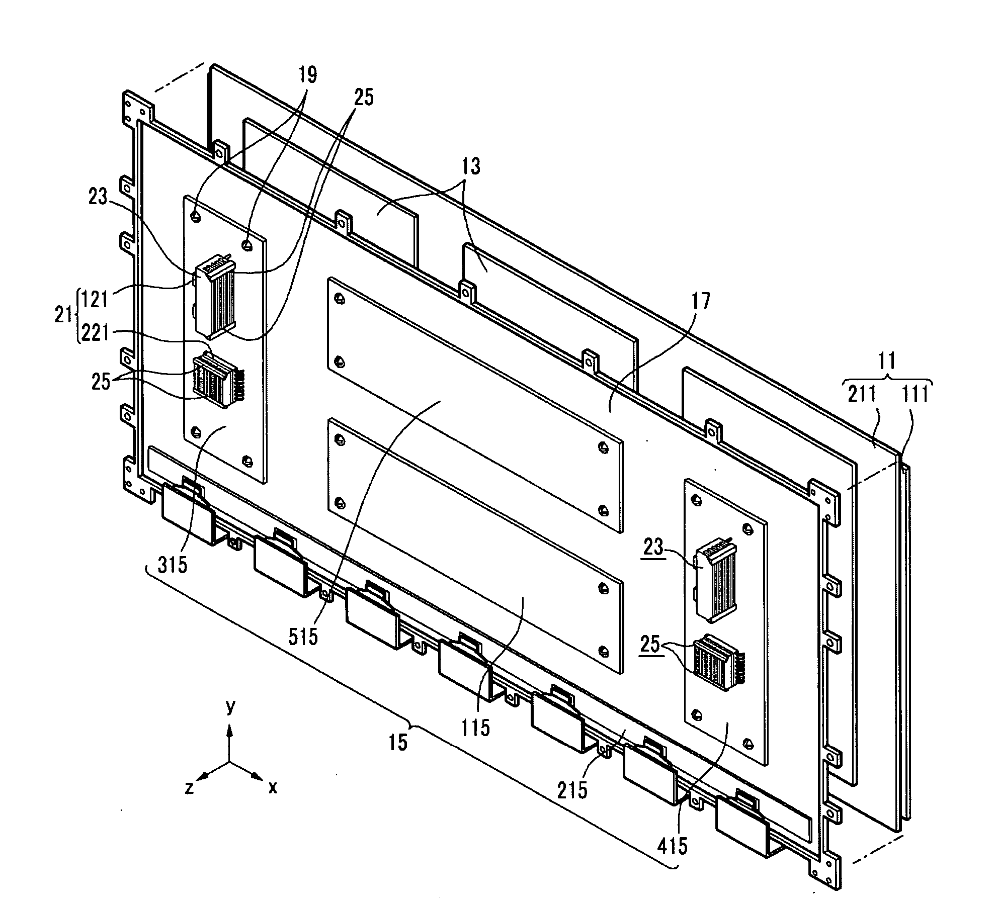
[0027] Referring to FIG. 1, a plasma display device according to the first exemplary embodiment of the present invention includes a PDP 11, a chassis base 17, and printed circuit board assemblies (PBAs) 15. The PDP 11 displays an image using a gas discharge. The chassis base 17 is attached to the rear side of the PDP 11. The PBAs 15 are mounted on the rear side of the chassis base 17, and are electrically connected to the PDP 11.

[0028] A heat dissipation sheet 13 and a double-sided adhesive tape (not shown) are interposed between the rear side of the PDP 11 and the front side of the chassis base 17. The heat dissipation sheet 13 dissipates heat generated by a gas discharge from the PDP in planar directions (x-y direction in FIG. 1).

[0029] The heat dissipation sheet 13 may be made of a heat dissipation material having sufficient thermal conductivity such as acryl, graphite, metal, or carbon nanotubes.

[0030] Since the double-sided adhesive tape attaches the PDP 11 to the chassis ba...


PUM


Abstract

A plasma display device to reduce noise generated from heat sinks. A chassis base is attached to a surface of a plasma display panel. A printed circuit board assembly is mounted to the chassis base at a side opposite to the plasma display panel and connected to the plasma display panel. The print circuit board assembly includes one or more circuit elements. A heat sink having a plurality of fins is attached to the one or more circuit elements. A fixing member connects and fixes free ends of the plurality of fins to one another.

Description

CROSS-REFERENCE TO RELATED APPLICATION [0001] This application claims priority to and the benefit of Korean Patent Application 10-2005-0044020 filed in the Korean Intellectual Property Office on May 25, 2005, the entire content of which is incorporated herein by reference. BACKGROUND OF THE INVENTION [0002] The present invention relates to a plasma display device, and more particularly, to a plasma display device in which noise generated from a heat sink is reduced. [0003] A plasma display device is an apparatus that displays an image on a plasma display panel (PDP) using plasma generated by a gas discharge. A PDP sustain driving board and a PDP scan driving board are provided with an intelligent power module (IPM) and a field effect transistor (FET) to control PDP sustain and scan electrodes. However, since the IPM and FET produce a substantial amount of heat during operation, the IPM and the FET are provided with heat sinks to dissipate the heat. The heat sinks also operate as noi...

Claims


Application Information

Patent Timeline
Patent Type & Authority Applications(United States)
IPC IPC(8): G09G3/28
CPCH05K7/20963H01J11/34H01J17/16H01J17/28H05K7/20409H05K7/20472
Inventor JEONG, KWANG-JIN
Owner SAMSUNG SDI CO LTD
Why Eureka
Try Eureka