
Stacked structure of power conversion apparatus

a technology of power converters and stacking structures, which is applied in the direction of power conversion systems, cooling/ventilation/heating modification, power electronics, etc., can solve the problems of less promoting effective utilization of heat sinks, and achieve the effect of reducing the overall size and reducing the cost of the power converter

Active Publication Date: 2014-05-13
FUJI ELECTRIC CO LTD
View PDF5 Cites 0 Cited by
  • Summary
  • Abstract
  • Description
  • Claims
  • Application Information

AI Technical Summary

Benefits of technology

The present invention aims to make efficient use of heat sinks to reduce the size, cost, and required fan capacity of power converters. By effectively utilizing heat sinks, the overall size of the power converter can be reduced, leading to cost reduction.

Problems solved by technology

However, when the number of parallel-connected modules is odd, contrary to the case when the number is even, dead space is created as shown in FIGS. 14 and 15 by the dotted line 21 (shown partially; the same applies for the rest), less promoting effective utilization of a heat sink.
However, because two IGBT modules in the V phase are arranged on the leeward side, those two modules have higher thermal load than the IGBT modules in the other phases, resulting in the requirement for a thermal design based on the V phase.

Method used


Image

  • Stacked structure of power conversion apparatus
  • Stacked structure of power conversion apparatus
  • Stacked structure of power conversion apparatus

Examples


Embodiment Construction

[0036]FIG. 6 shows a main circuit diagram of a power converter such as, for example, an inverter. In this figure, 11 is a DC (direct current) power source (circuit), 12 is load such as a motor (Mo), and 13 is a power converting part (inverter) consisting of power semiconductor elements which can provide an alternating current (AC) output of a variable voltage and frequency. The DC power source (circuit) 11 may be generally composed of an electrolytic capacitor having large capacitance through an AC power source and a diode rectifier.

[0037]In the inverter 13, the numeral 14 represents an IGBT (Insulated Gate Bipolar Transistor) as a switching element and 15 represents a diode which is connected in anti-parallel to the IGBT, and 6 circuits respectively comprising these elements compose the inverter. The IGBT module may be composed of a pair of two, upper and lower, elements or of a set of six elements. An inverter providing an output in three phases and having a capacitance above a ce...


PUM


Abstract

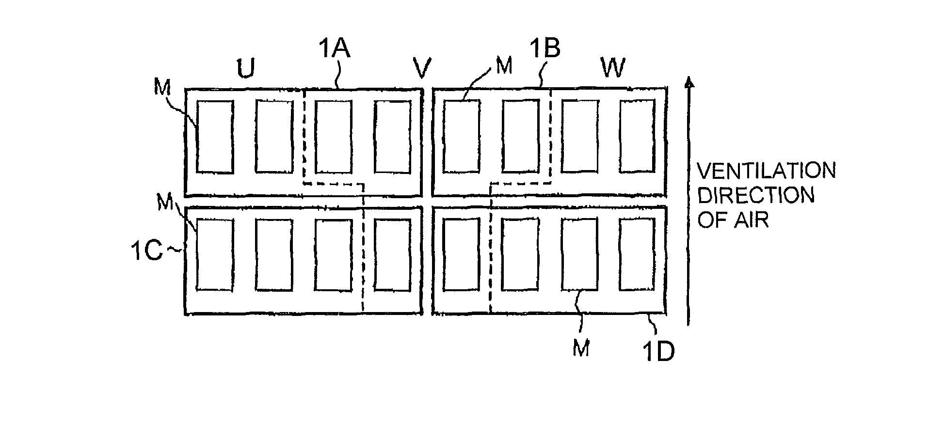
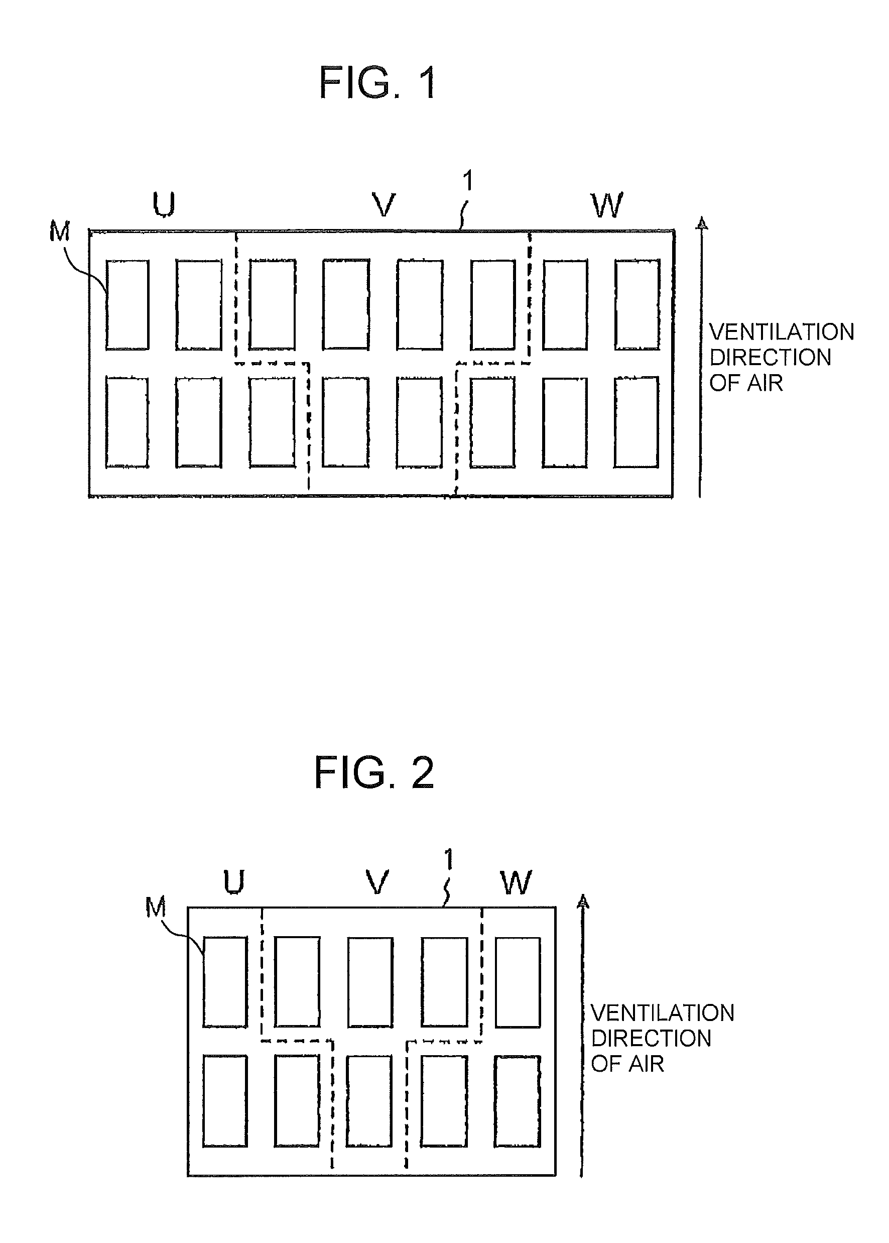
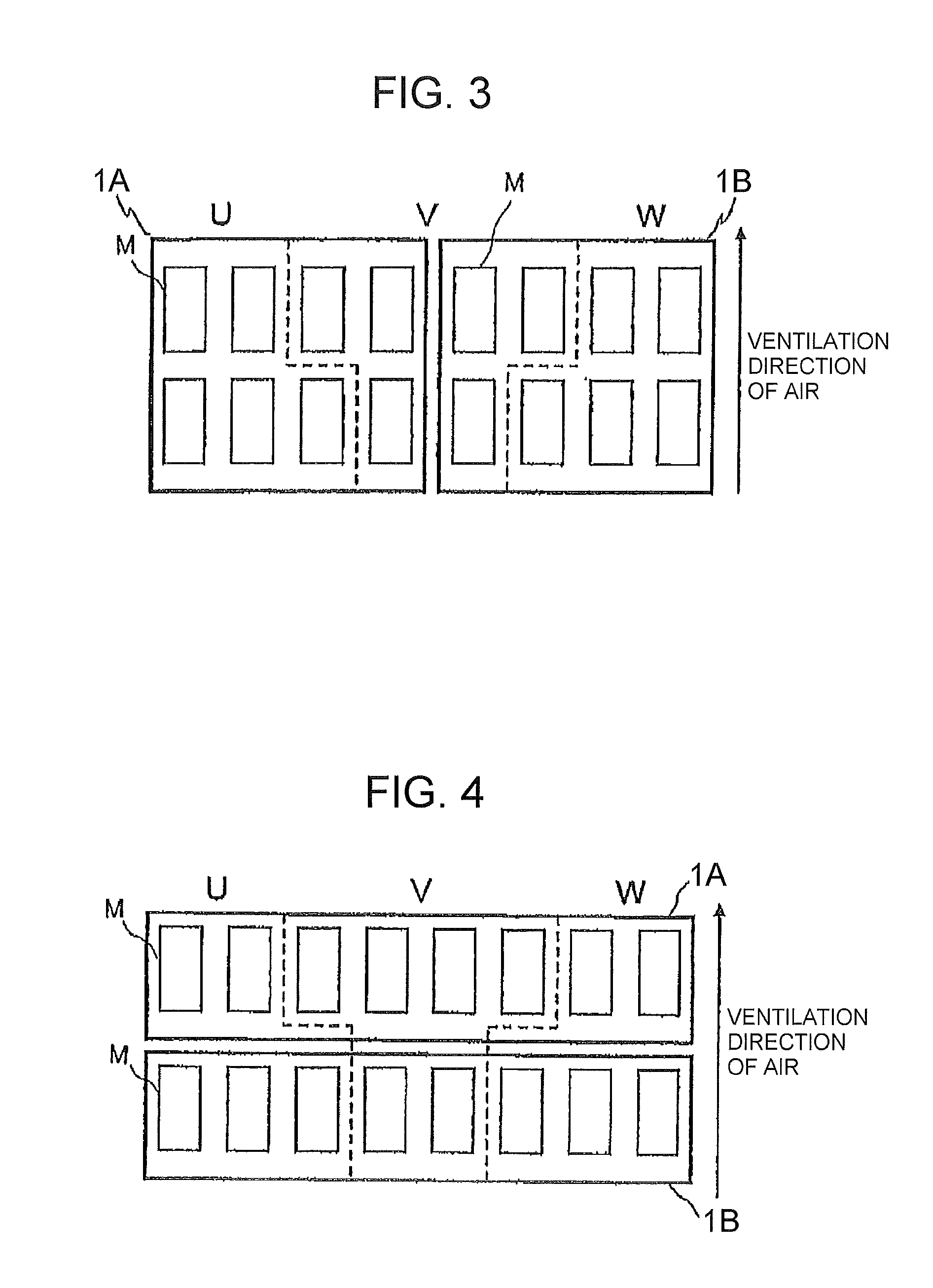
A stacked structure of a power converter is disclosed. The stacked structure has a power conversion circuit that provides an output or input of alternating current in three phases and is composed of odd-numbered parallel-connected power semiconductor element modules for each phase, and a heat sink for cooling the power semiconductor element modules. An odd number of the parallel-connected power semiconductor element modules are arranged in a first phase and a third phase, and an even number of the parallel-connected power semiconductor element modules are arranged in a second phase respectively in two rows on the heat sink relative to a ventilation direction of air for cooling the heat sink.

Description

CROSS REFERENCE TO RELATED APPLICATION[0001]The entire disclosure of the inventor's corresponding Japanese patent application, Serial No. JP PA 2011-013252, filed Jan. 25, 2011, is hereby incorporated by reference.BACKGROUND OF THE INVENTION[0002]1. Field of the Invention[0003]The present invention relates to a stacked structure of a power converter configured by connecting power semiconductor modules in parallel.[0004]2. Description of the Related Art[0005]IGBT modules generally require a heat sink for cooling heat due to generation loss. A typical aluminium heat sink is shown in FIG. 9. It usually has a shape of a rectangular solid, is composed of a heat reception part 19 and a fin part 20 and effects cooling by ventilating the fin part 20. Three IGBT modules, according to the example shown in FIG. 7, connected in parallel are placed in the heat reception part as nine modules of all phases or as separate phases each containing three modules, as shown in FIGS. 10 and 11, respective...

Claims


Application Information

Patent Timeline
Patent Type & Authority Patents(United States)
IPC IPC(8): H02M7/537
CPCH02M7/003H05K7/20909
Inventor TAKIZAWA, SATOKI
Owner FUJI ELECTRIC CO LTD
Learn More