
LED lamp with active chamber cooling

a technology of led lamps and active chambers, which is applied in outdoor lighting, lighting and heating apparatus, lighting applications, etc., can solve the problems of reducing efficiency at angles greater than 12 degrees, and achieve the effect of reducing efficiency, reducing the desired thermal draw through the heat sink, and reducing the desired thermal draw

Inactive Publication Date: 2018-12-04
TITAN LED INC
View PDF2 Cites 0 Cited by
  • Summary
  • Abstract
  • Description
  • Claims
  • Application Information

AI Technical Summary

Benefits of technology

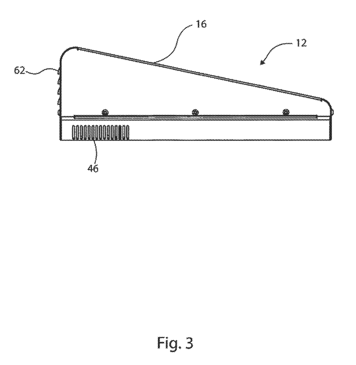
The present invention LED lamp has cooling fans mounted at an angle of about 10 degrees from horizontal to direct the airflow into the second or hot chamber in a downward and forward direction in regards to the heat sink. The mounting angle of the fans is critical to assist the thermal wicking function of the heat sink fins. Efficiency is reduced at angles of greater than about 12 degrees because the airflow passes too rapidly through the fins of the heat sink reducing the desired thermal draw through the heat sink, and at angles of lower than about 8 degrees because the airflow is partially blocked by the heat sink resulting in less airflow through the fins and reducing the thermal wicking function of the heat sink fins. The LED lamp also configures the mid-plate such that a portion of the mid-plate lays flat across top edges or surfaces of the heat sink fins creating individual channels or thermal transfer chambers between the fins. This feature is critical for the efficient and effective thermal dynamics of the heat sink promoting the greatest thermal wicking effect and preventing the heat sink from reaching saturation.

Problems solved by technology

Efficiency is reduced at angles of greater than about 12 degrees because the airflow passes too rapidly through the fins of the heat sink reducing the desired thermal draw through the heat sink.

Method used


Image

  • LED lamp with active chamber cooling
  • LED lamp with active chamber cooling
  • LED lamp with active chamber cooling

Examples


Embodiment Construction

[0030]The present invention will now be described more fully hereinafter with reference to the accompanying drawings, in which preferred embodiments of the invention are shown. The invention may, however, may be embodied in many different forms and should not be construed as being limited to the embodiments set forth herein. Rather these embodiments are provided so that this disclosure will be thorough and complete, and will fully convey the scope of the invention to those skilled in the art. Like numbers refer to like elements throughout.

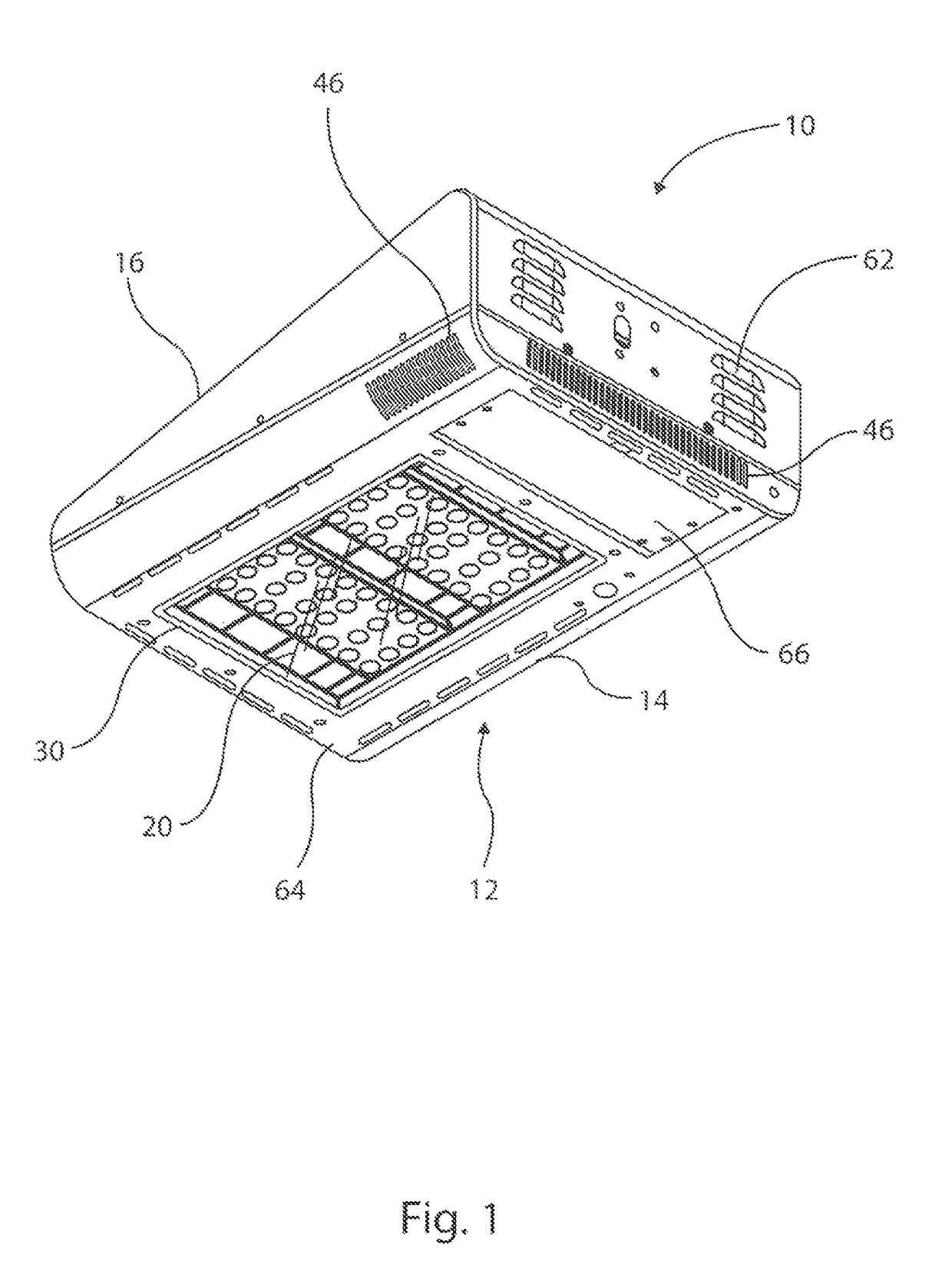
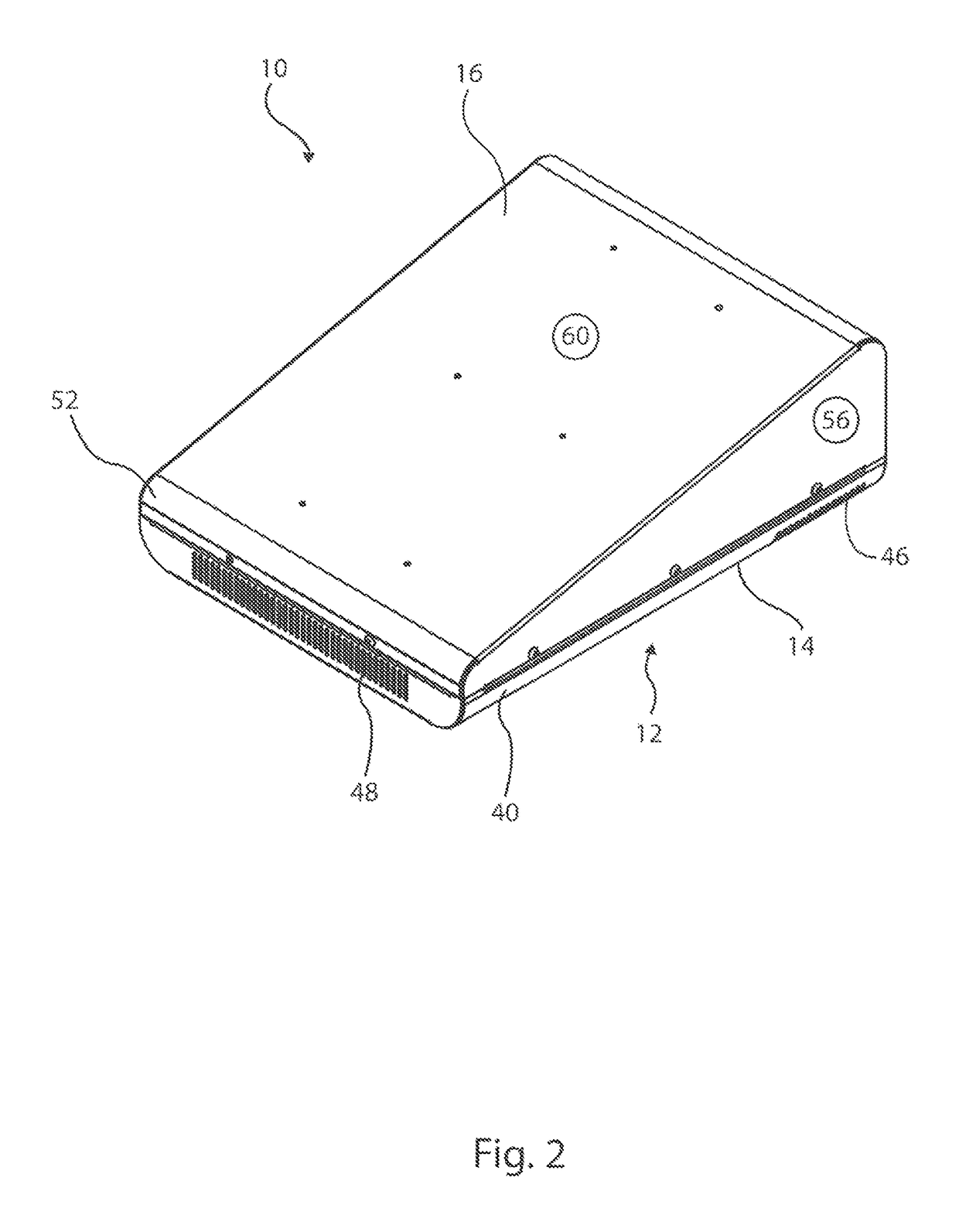
[0031]With reference to FIGS. 1-16, and particular reference to FIGS. 1 and 7-9, an LED lamp 10 in accordance with the present invention is presented. The LED lamp 10 comprises generally a housing 12 where the housing includes a base 14, a case cover 16 and a mid-plate 24. Enclosed within the housing 12 are a plurality of LED modules 18 (see FIG. 8), a lens plate 20, a heat sink 22, a plurality of cooling fans 26, and an LED driver 28 (see FIG. 9)....


PUM


Abstract

An LED lamp employing active cooling chambers is presented. The lamp features a housing having two active cooling chambers. One chamber, i.e. the first or cold chamber, contains an LED driver and one or more cooling fans, while the second chamber, i.e. the hot chamber, contains one or more LED modules secured to a heat sink. Fluid (air) communication between the two chambers is controlled by the one or more cooling fans. In operation, the fans draw ambient cooling air inside the cold chamber via air intake openings in the housing. The cooling air is then forced through a plurality of heat sink fins and heat transfer channels and exhausted from air exhaust openings in the housing.

Description

CROSS-REFERENCE TO RELATED APPLICATIONS[0001]This patent application claims priority from U.S. Utility Application Ser. No. 62 / 148,016 entitled “LED Lamp with Active Chamber Cooling,” filed on Apr. 15, 2015, which is incorporated herein by this reference.BACKGROUND OF THE INVENTION[0002]Field of the Invention[0003]The present invention relates generally to light-emitting diode (“LED”) area lamps using a plurality of LEDs operating at relatively high wattages in commercial applications including warehouse, high bay and parking lot applications and more particularly, to housings incorporating features for cooling such lamps.[0004]Background of the Invention[0005]Solid state lamps or lights utilizing arrays of LEDs are now gaining favor for use in a variety of applications including general indoor and outdoor area lighting of commercial warehouse, high bay and parking lot facilities, among a growing list of commercial and residential applications. Lighting systems utilizing LED arrays ...

Claims


Application Information

Patent Timeline
Patent Type & Authority Patents(United States)
IPC IPC(8): F21S45/40F21V29/67F21V29/00F21V29/74F21V5/04F21V23/00F21W131/103F21W131/40
CPCF21V29/673F21V5/04F21V29/74F21V23/003F21W2131/40F21W2131/103
Inventor BROWN, BRIANHENNESSY, BRIANSANDERS, KEVIN
Owner TITAN LED INC
Learn More