
Encompassing Heat Sink

a heat sink and electromagnetic technology, applied in the direction of electrical equipment, solid-state devices, cooling/ventilation/heating modification, etc., can solve the problems of components inside the computer that are susceptible to radiation heat energy, and achieve the effect of reducing convective energy, reducing movement, and improving thermal heat extraction efficiency

Inactive Publication Date: 2007-01-25
GRAVINA MATTEO B
View PDF21 Cites 0 Cited by
  • Summary
  • Abstract
  • Description
  • Claims
  • Application Information

AI Technical Summary

Benefits of technology

"The present invention is an improvement of heat sinks used in central processor units. The invention emphasizes the use of a side heat extraction design on the heat sink, which allows for more efficient extraction of heat energy from the processor. By doing so, the heat sink reduces the convective energy and prevents it from moving onto surrounding areas of the processor. This results in improved thermal heat extraction efficiency and reduced inefficiency of software working parameters. The heat sink also enables the microprocessor to execute orders and requests from open applications, reducing the struggle it faces in executing these operations. The more heat energy the heat sink extracts, the less heat energy stays resident in the processor, leading to improved performance and reduced inefficiency of connected and interconnected devices."

Problems solved by technology

Since the air is constantly moving throughout the surrounding areas of the CPU close components inside the computer are susceptible of receiving radiation heat energy.

Method used


Image

  • Encompassing Heat Sink
  • Encompassing Heat Sink
  • Encompassing Heat Sink

Examples


Embodiment Construction

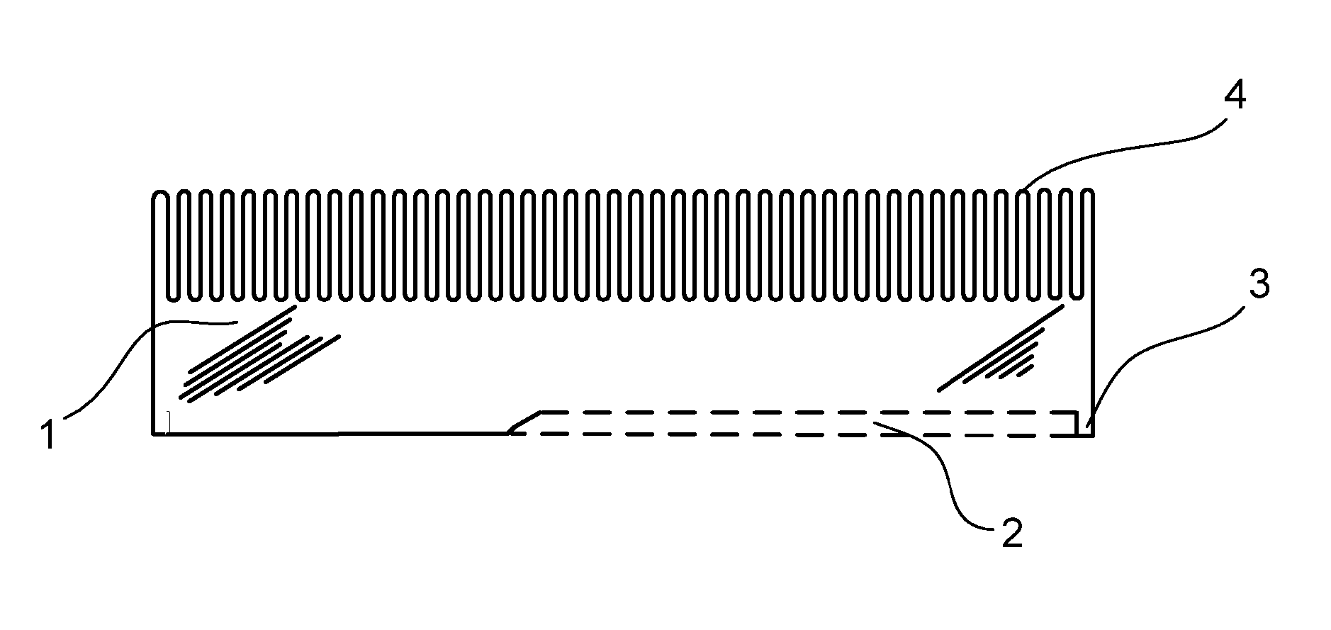
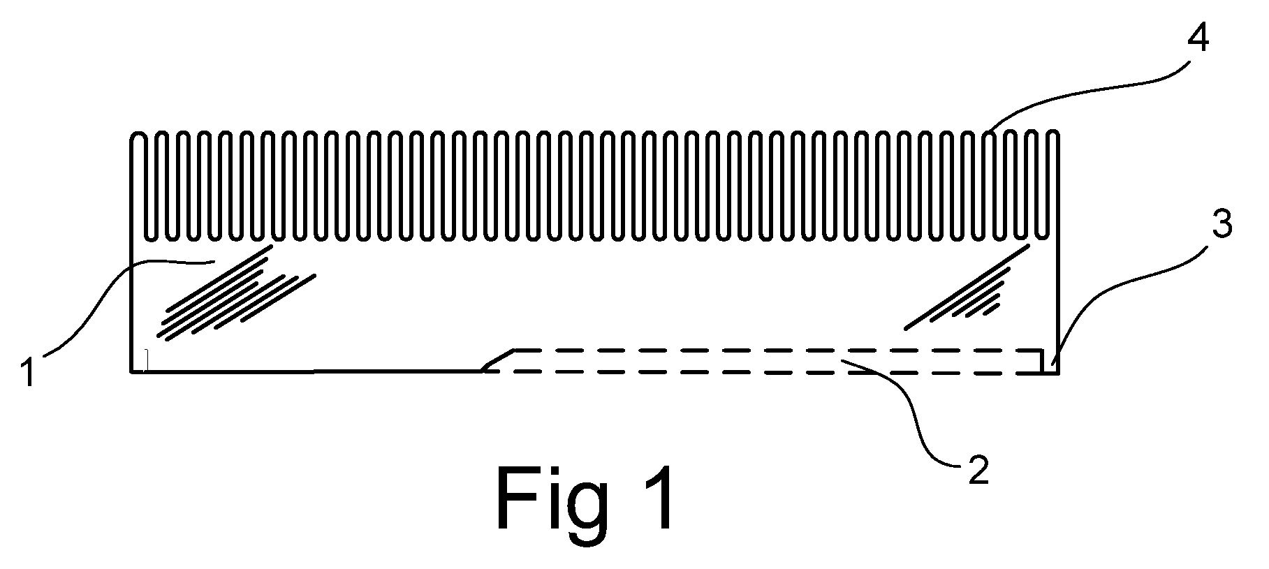
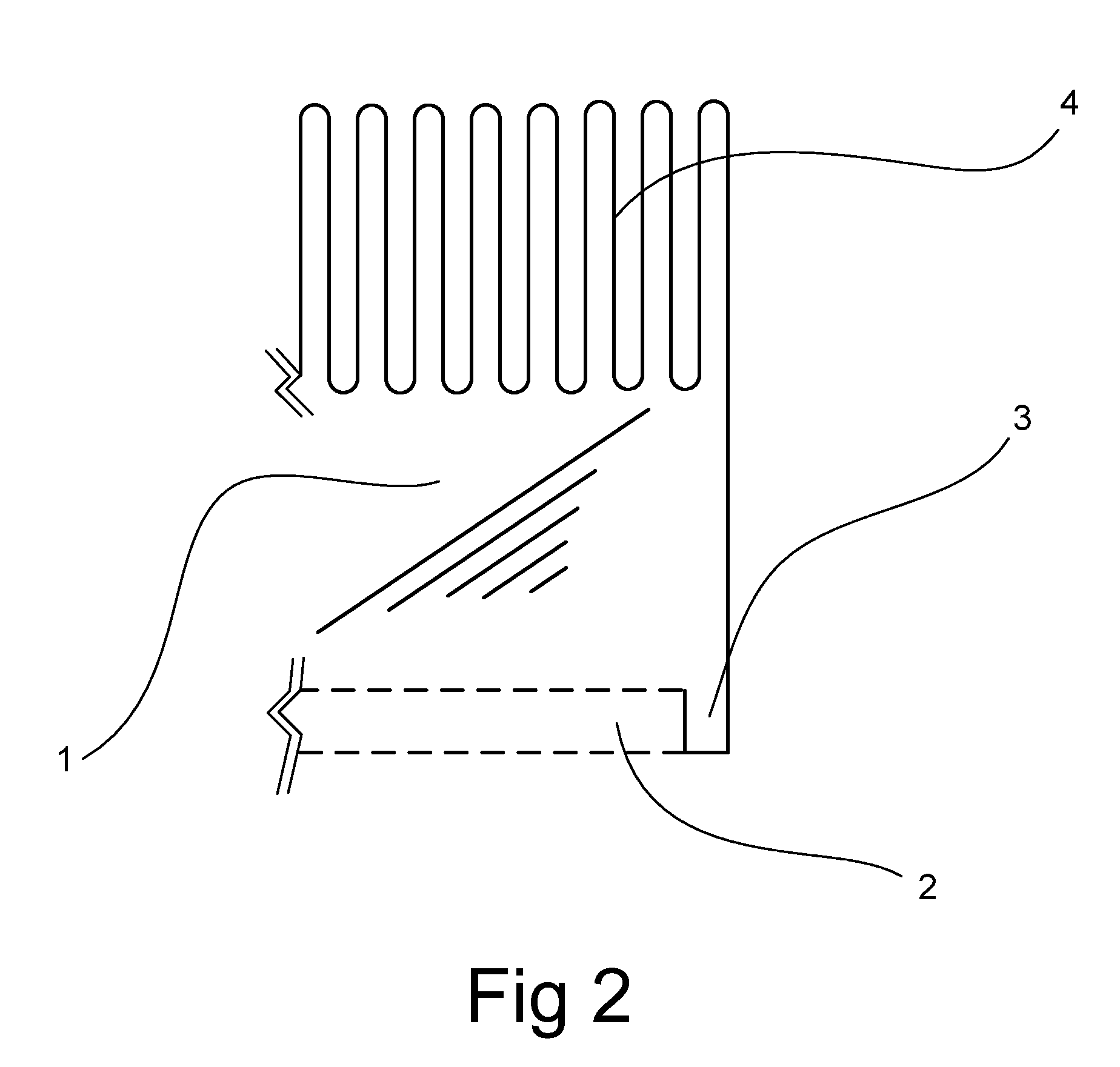
[0012]FIG. 1 is a side view of the encapsulating heat sink on top of a microprocessor. The encapsulating heat sink is device by its (1) main body which receives most convection radiation of heat energy. To the left side in the corner a cutout view of the (2) depression is view, at the end is the (3) encapsulating arm which receives convective energy that would otherwise prolong at the CPU. The encapsulating heat sink has on top an assortment of (4) grills which permit air passage to cool the heat sink. At the bottom of FIG. 3 is the microprocessor which is retains within the central processor chip inside, its typical design is encapsulation of the microprocessor chip by an (5) CPU ceramic protection. At the center is lies the microchip which is usually protected by a (7) microprocessor chip housing. At surrounding attach to the (5) CPU ceramic protection are (6) Ziff socket pins.

[0013] In FIG. 2 is the encapsulating heat sink with a partial view. The exploded insertion illustrates ...


PUM


Abstract

This invention relates to a microprocessor heat sink that is place on top of a central processing unit, which at the same time encompasses the sides of the processing unit. It consists of an upper block which receives heat from the processing unit, at the same time the heat sink envelopes the sides of the microprocessor thereby encompassing also its sides. By encompassing the sides of the microprocessor, the heat emitted by the processor are pass along to the heat sinks enveloping arms.

Description

FIELD OF THE INVENTION [0001] The present invention relates to semiconductor thermal transfer, moreover microprocessor cooling. BACKGROUND OF THE INVENTION [0002] The advent of the modern electronics is analogous with computers. The birth of the microprocessor in the 1970's lead to the creation of the modern desktop computer. At its initial creation the Central Processing Unit of the time was a basic mathematical calculating device. With technological growth in the 1980's the first's personal computers came of age, with them faster and more complex microprocessors. With skillful marketing and technology allowing consumers access to computers, micro processing capabilities would be forced to new heights. The initial processing was 4-bit, then came the 8-bit, 16-bit, which has mature to the modern 32-bit processing units. With this eventual growth the microprocessor has mature into a very complex very large scale integration device. [0003] With exceptional growth in software, hardware...

Claims


Application Information

Patent Timeline
Patent Type & Authority Applications(United States)
IPC IPC(8): H05K7/20
CPCH01L23/367H01L2924/0002H01L2924/00
Inventor GRAVINA, MATTEO B.
Owner GRAVINA MATTEO B
Learn More