

Method and apparatus for improving image quality
a technology of image quality and display apparatus, which is applied in the field of methods and apparatus for improving the image quality of display apparatus, can solve the problems of blurred moving image, reduced luminance, and high cost, and achieve the effect of restraining blur in moving image without reducing luminance and low cost image quality
- Summary
- Abstract
- Description
- Claims
- Application Information
AI Technical Summary
Benefits of technology
Problems solved by technology
Method used
Image

Examples
embodiment (
Embodiment(s) of the Invention
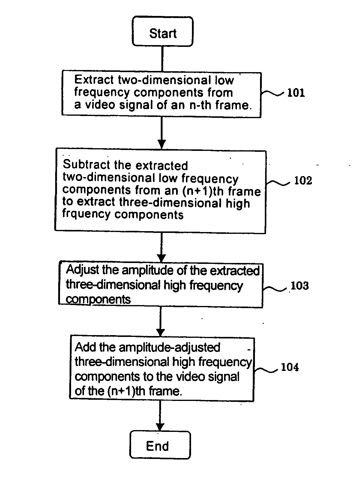
[0042] Referring now to the drawings, and more particularly to FIGS. 1-14, there are shown exemplary embodiments of the method and apparatus of the present invention.
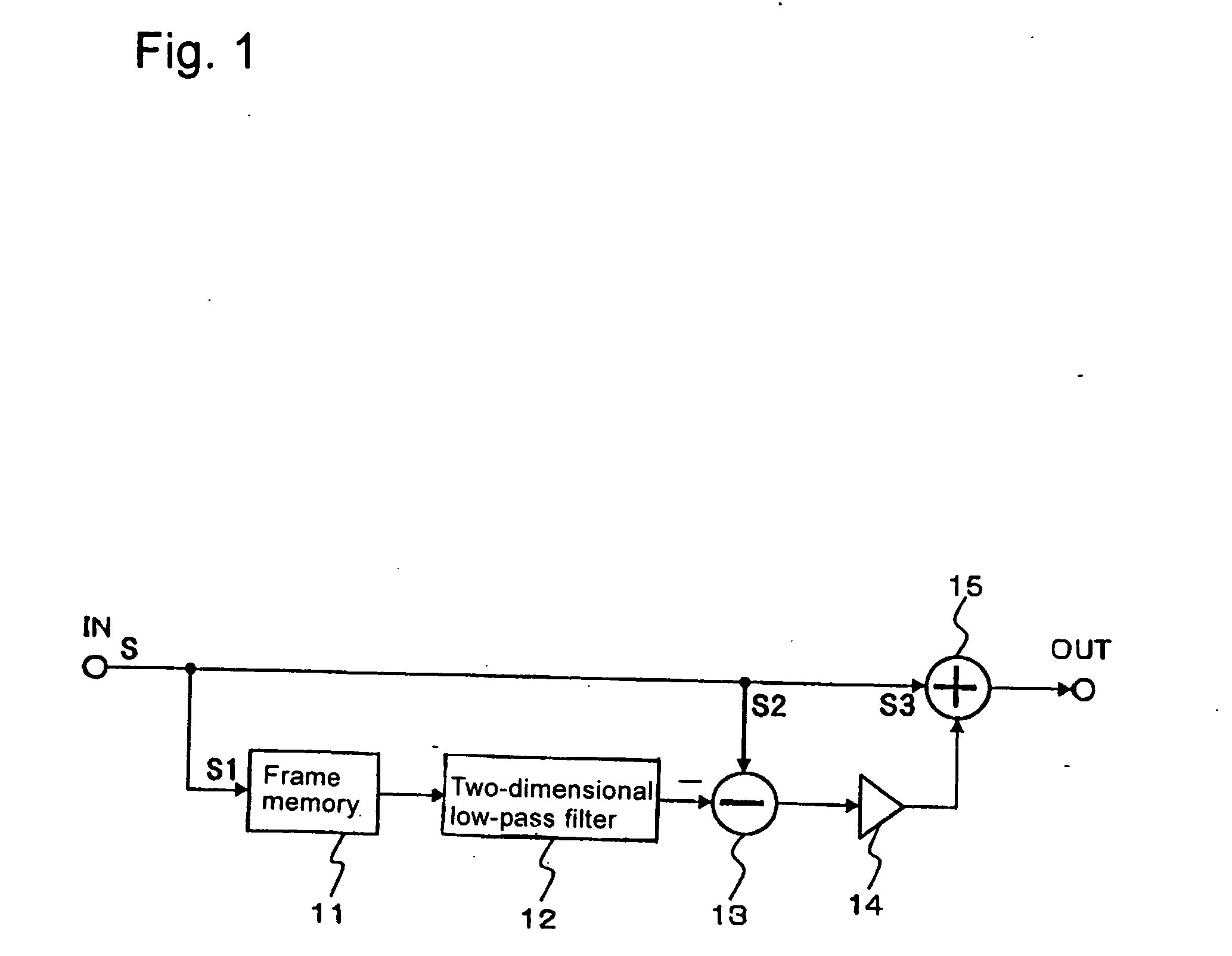
[0043]FIG. 1 is a block diagram generally illustrating the configuration of an image quality improving apparatus according to an exemplary embodiment of the present invention. Referring to FIG. 1, the image quality improving apparatus of this exemplary embodiment may include frame memory 11, two-dimensional low-pass filter 12, subtractor 13, multiplier 14, and adder 15.
[0044] Video signal S fed from input terminal IN is supplied to frame memory 11, subtractor 13, and an adder 15, respectively. Here, the video signal supplied to frame memory 11 is designated by reference S1; the video signal supplied to subtractor 13 is designated by reference S2; and the video signal supplied to adder 15 is designated by reference S3.
[0045] Frame memory 11 delays video signal S1 supplied from input termi...
example 1
[0078]FIG. 8 is a block diagram illustrating the configuration of part of the image quality improving apparatus according to a first example of the present invention. The configuration illustrated in FIG. 8 may correspond to the configuration which includes frame memory 11 and two-dimensional low-pass filter 12 shown in FIG. 1, and includes horizontal low-pass filter 21, down-sampler 22, frame memory 23, vertical low-pass filter 24, and up-sampler 25.
[0079] Horizontal low-pass filter 21 extracts horizontal low frequency components from a video signal supplied from input terminal IN. A video signal which includes the horizontal low frequency components extracted by horizontal low-pass filter 21 is supplied to down-sampler 22.
[0080] Down-sampler 22 reduces the sampling rate of the video signal. Specifically, in down-sampler 22, when reducing the sampling rate to one half, frequency bands are limited by a low-pass filter such that the frequency components of the input signal fall wit...
example 2
[0088]FIG. 9 is a block diagram illustrating the configuration of part of an image quality improving apparatus according to a second exemplary aspect of the present invention. The configuration illustrated in FIG. 9 may correspond to the configuration which includes frame memory 11 and two-dimensional low-pass filter 12 shown in FIG. 1, and may include IIR filters 31, 33 and frame inverters 32, 34.
[0089] IIR filters 31, 33 may include (e.g., may each include) a general low-pass filter which includes a circular filter. FIG. 10 illustrates a configuration of an IIR filter, and FIG. 11 shows the impulse response thereof. As illustrated in FIG. 10, the IIR filter comprises two coefficient multipliers 41, 42, adder 43, and delay element 44.
[0090] The output of coefficient multiplier 41 is supplied to one input of adder 43. The output of adder 43 is branched into two, one of which provides output OUT, and the other of which is supplied to delay element 44. The output of delay element 44...
PUM
 Abstract
Description
Claims
Application Information