Imaging Systems Using Unpolarized Light And Related Methods And Controllers

a technology of unpolarized light and imaging system, applied in the field of imaging systems, can solve the problems of no means for minimizing or controlling polarization fading, and interfering with a static reduction in polarization efficiency of about 50%

Active Publication Date: 2007-04-19
BIOPTIGEN
View PDF22 Cites 167 Cited by
  • Summary
  • Abstract
  • Description
  • Claims
  • Application Information

AI Technical Summary

Benefits of technology

[0045] In some embodiments of the present invention, the optical imaging system operates using substantially unpolarized light. The birefringence controller may be further configured to have a single degree of freedom and wherein the single degree o...

Problems solved by technology

Under certain conditions, unpolarized light interferes with a static reduction in polarization efficiency of about 50%.
In this configuration, no means...

Method used


Image

  • Imaging Systems Using Unpolarized Light And Related Methods And Controllers
  • Imaging Systems Using Unpolarized Light And Related Methods And Controllers
  • Imaging Systems Using Unpolarized Light And Related Methods And Controllers

Examples


Embodiment Construction

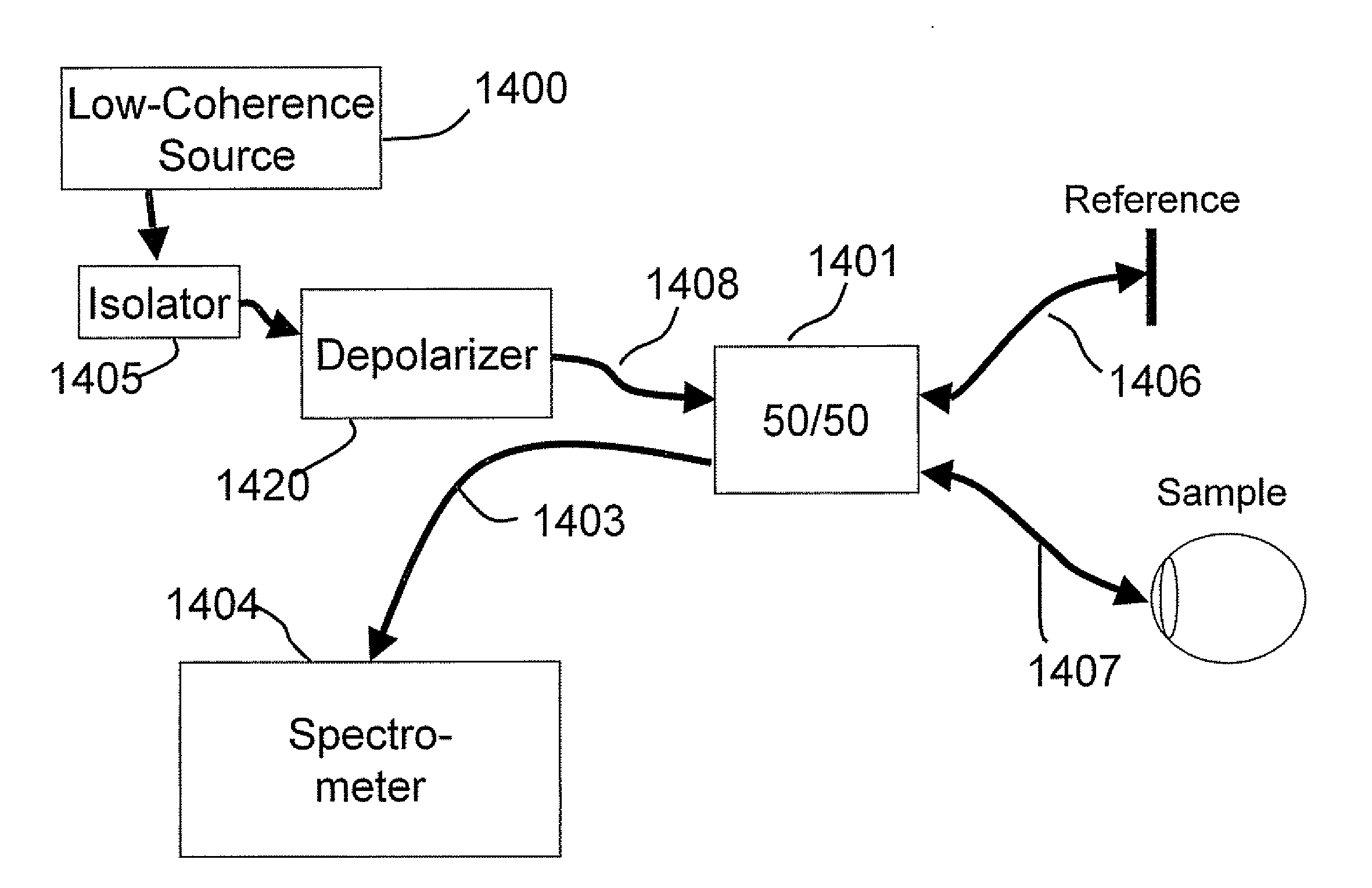
[0015] Some embodiments of the present invention provide optical imaging systems including a light source and a depolarizer. The light source is provided in a source arm of the optical imaging system. A depolarizer is coupled to the light source in the source arm of the optical imaging system and is configured to substantially depolarize the light from the light source.

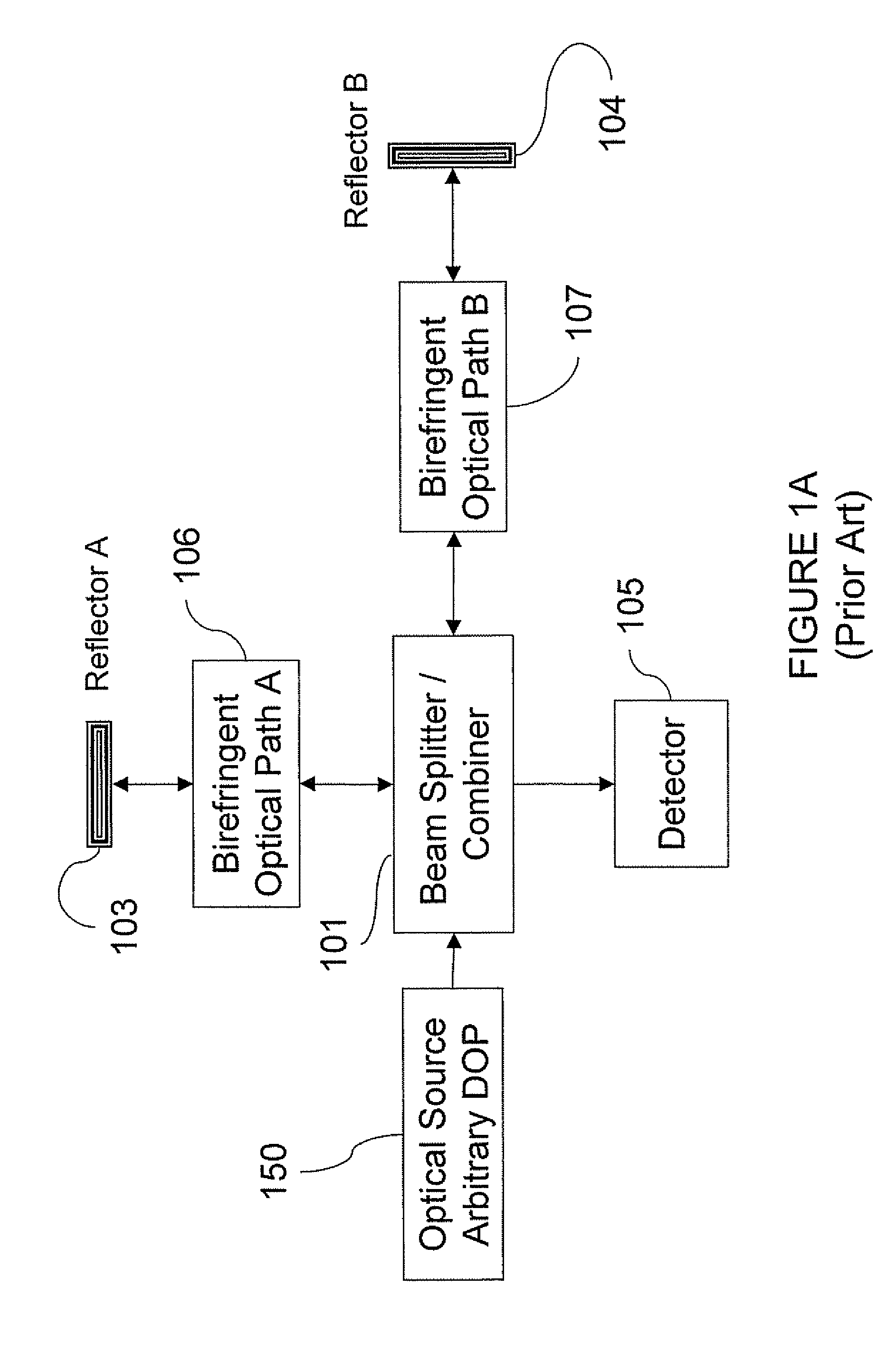
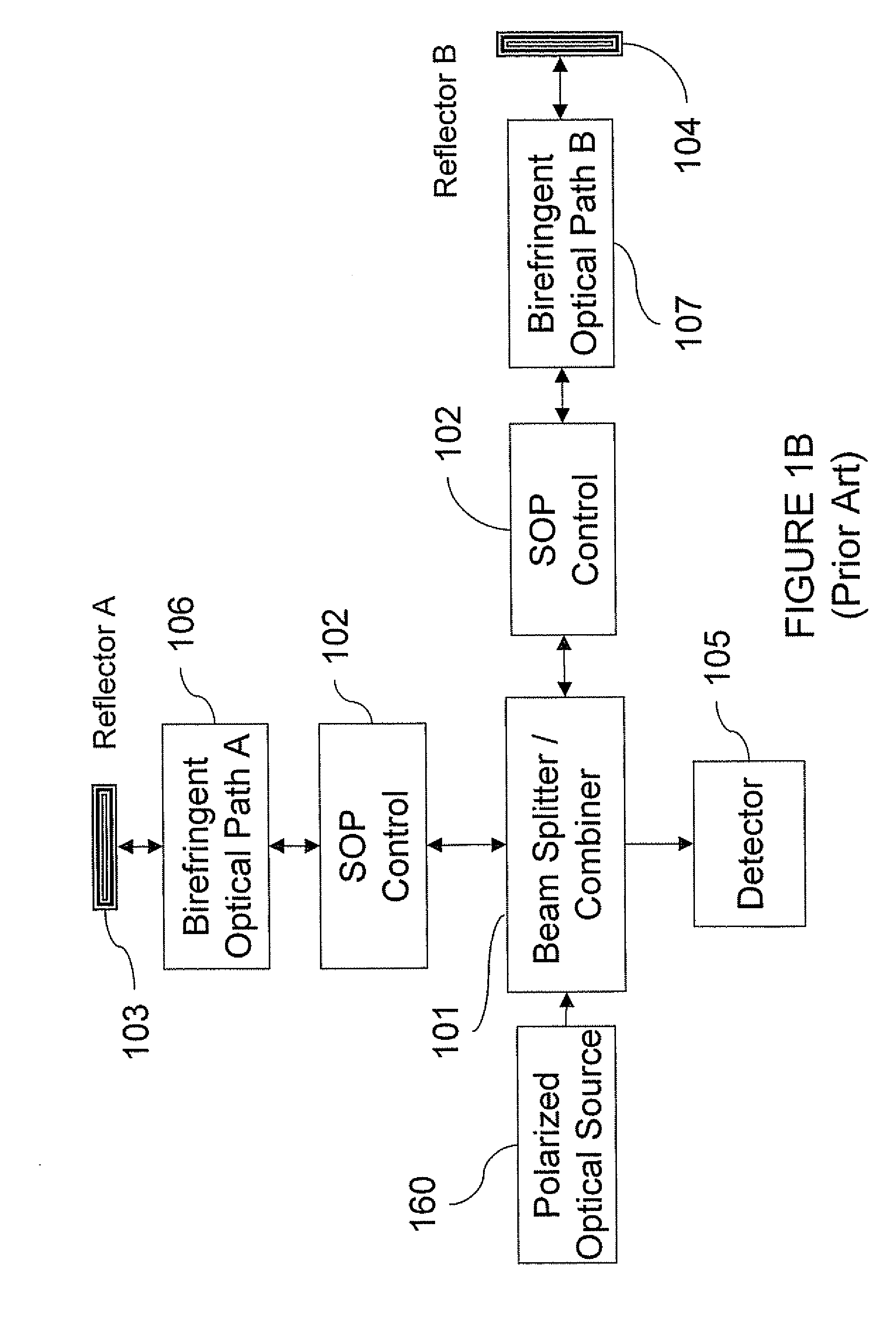
[0016] In further embodiments of the present invention, a birefringence controller may be provided in a first path or a second path of the system and may be configured to modify a polarization-dependent optical path length in the at least one of the first and second paths. In certain embodiments of the present invention, control settings of the birefringence controller may be set during manufacture and configured to be adjusted infrequently. In further embodiments of the present invention, control settings of the birefringence controller may be dynamic and may be configured to be set based on a metric of a measured o...


PUM


Abstract

Optical imaging systems are provided including a light source and a depolarizer. The light source is provided in a source arm of the optical imaging system. A depolarizer is coupled to the light source in the source arm of the optical imaging system and is configured to substantially depolarize the light from the light source. Related methods and controllers are also provided.

Description

CLAIM OF PRIORITY [0001] The present application claims priority from U.S. Provisional Application No. 60 / 725,087 (Attorney Docket No. 9526-3PR), filed Oct. 7, 2005, the disclosure of which is hereby incorporated herein by reference as if set forth in its entirety.FIELD OF THE INVENTION [0002] The present invention relates to imaging and, more particularly, to imaging systems and related methods and controllers. BACKGROUND OF THE INVENTION [0003] There are a variety of approaches to imaging in general. One approach is optical coherence tomography (OCT). OCT systems include Fourier domain OCT (FD-OCT) and time domain OCT (TD-OCT). FD-OCT generally includes swept source (SS) and spectral domain (SD), where SD systems generally use spectrometers rather than a swept source. TD systems generally rely on movement of a mirror or reference source over time to control imaging depth. In contrast, for FD-OCT, the imaging depth may be determined by Fourier transform relationships between the ac...

Claims


Application Information

Patent Timeline
IPC IPC(8): G01B9/02G01J3/45G01B11/02
CPCA61B3/102A61B3/1225A61B5/0066G01N21/23G01N21/45G01N2021/1787G01B9/02004G01B9/02044G01B9/02027G01B9/02091G01B2290/70G01B2290/45
Inventor BUCKLAND, ERIC L.MARCIANTE, JOHN R.IZATT, JOSEPH A.BROWN, WILLIAM J.
Owner BIOPTIGEN
Why Eureka
Try Eureka