Method of forming a head suspension with an integral boss tower

a head suspension and integral technology, applied in the direction of maintaining the alignment of the head carrier, recording information storage, instruments, etc., can solve the problems of unsatisfactory miniaturization of the swage plate, the recent move to disk-to-disk spacing of under two millimeters has presented a severe problem, etc., to reduce the mass and inertia of the head suspension, reduce the size of the head stack assembly, and reduce the effect of disk spacing

Inactive Publication Date: 2007-04-19
INTRI PLEX (THAILAND) LTD
View PDF21 Cites 5 Cited by
  • Summary
  • Abstract
  • Description
  • Claims
  • Application Information

AI Technical Summary

Benefits of technology

[0012] The present invention is directed to a head suspension assembly with a mounting region comprising an integral boss tower. The integral boss tower can be formed from material comprising the mounting region or as a separate component attached directly to the mounting region without a base plate. The integral boss tower eliminates the base plate and reduces the size of the head stack assembly, and hence, reduces disk spacing. The elimination of the base plate also reduces mass and inertia of the head suspension. The present integral boss tower can be used to mount a head suspension assembly to an actuator arm using industry-accepted standards.

Problems solved by technology

However, recent moves to disk-to-disk spacing of under two millimeters have presented a severe problem.
Miniaturization of the swage plates is not satisfactory because the torque-out capability that the swaged system drops too low to be useful.

Method used


Image

  • Method of forming a head suspension with an integral boss tower
  • Method of forming a head suspension with an integral boss tower
  • Method of forming a head suspension with an integral boss tower

Examples


Embodiment Construction

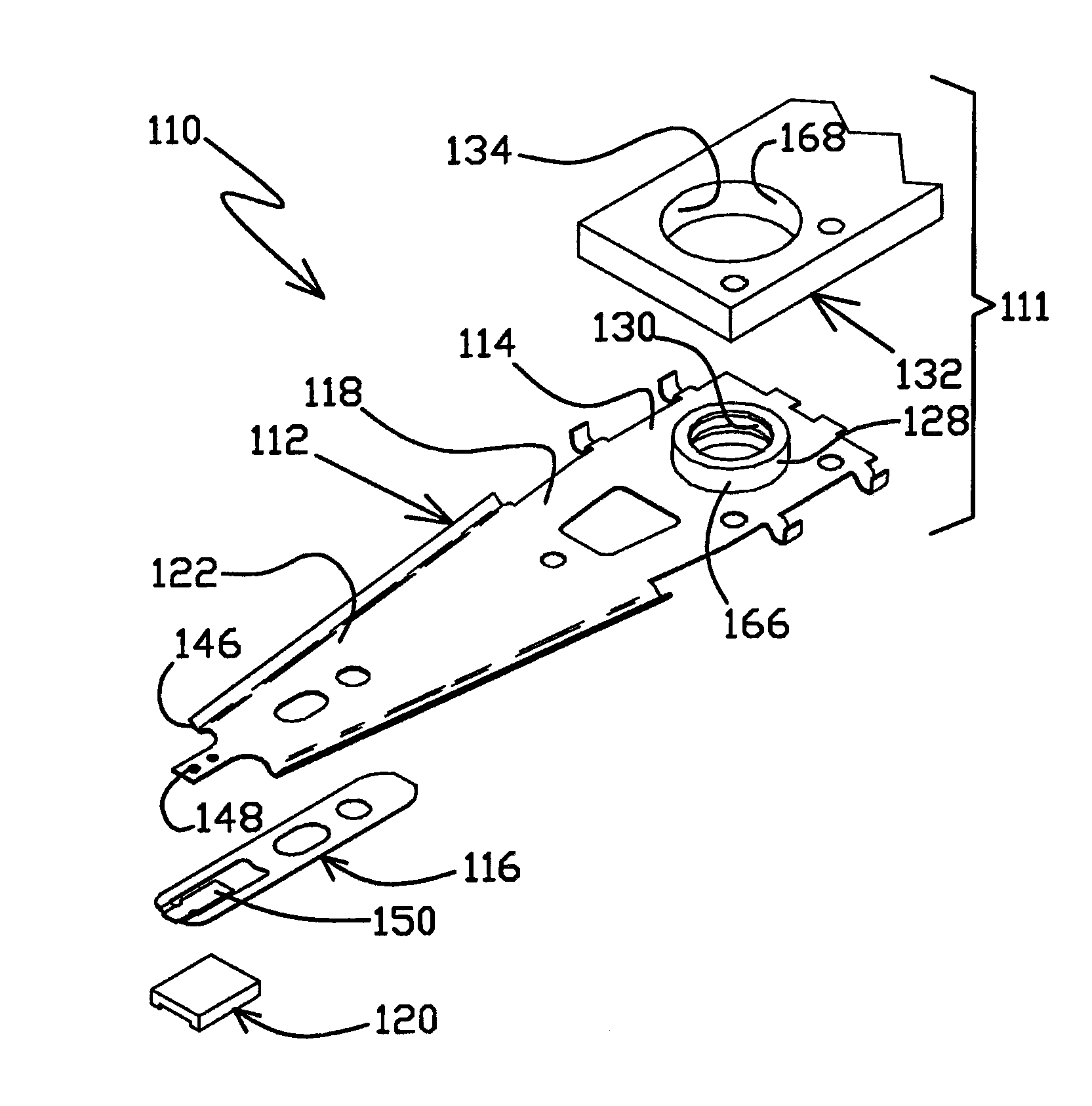
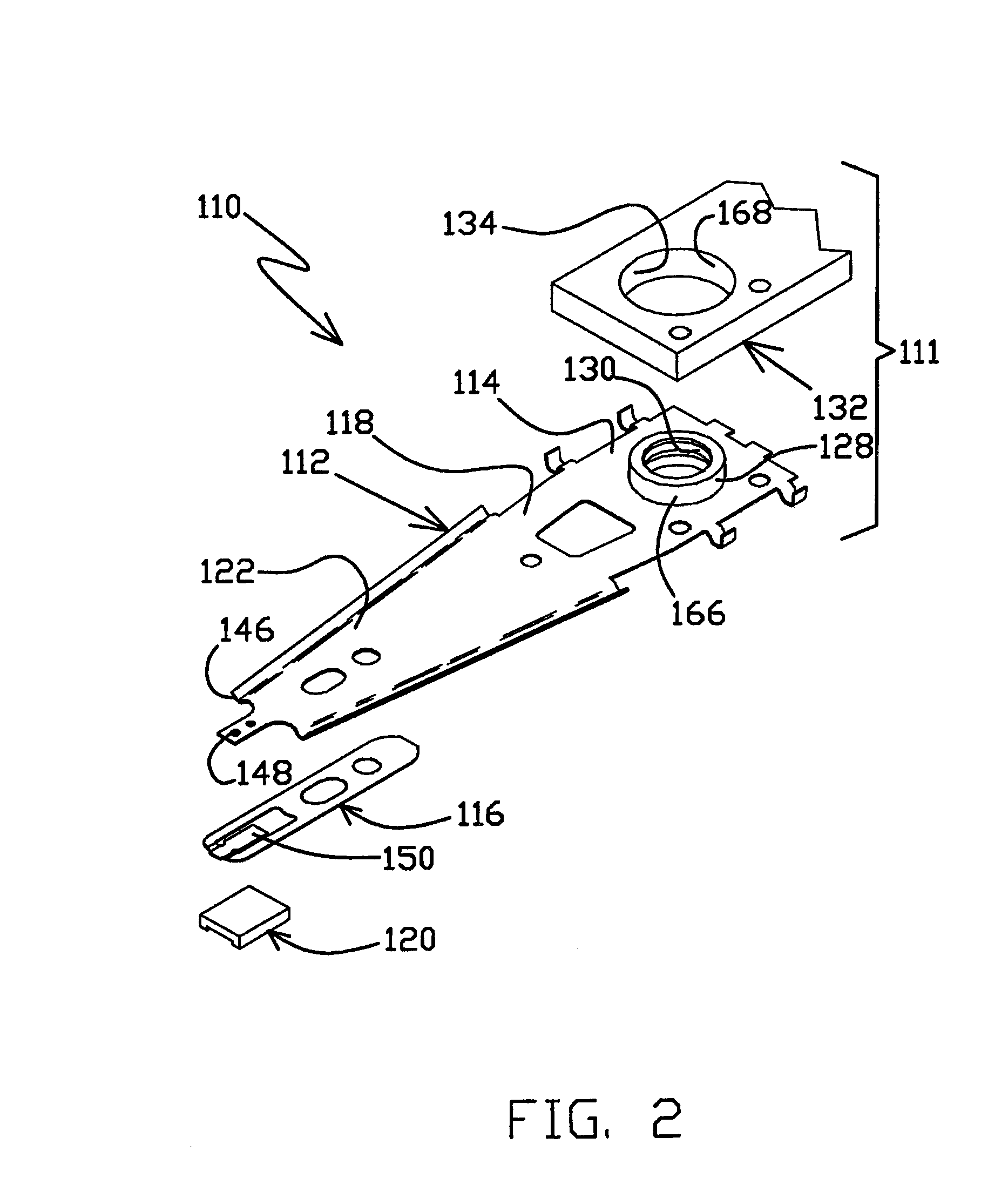
[0034]FIG. 2 is an exploded, isometric view of a head stack assembly 111 including a head suspension assembly 110 and an actuator arm 132. The head suspension assembly 110 includes a load beam 112 with a flexure 116 to which a head slider 120 having a read / write element or head mounted at a slider mounting surface 150. Slider mounting surface 150 on flexure 116 in combination with dimple 148 on distal end 146 allows pitch and roll motion of head slider 120 and read / write head as they move over the data tracks of the disk.

[0035] The load beam 112 includes a mounting region 114 at a proximal end, a rigid region 122 adjacent to a distal end and a spring region 118 between the mounting region 114 and rigid region 122. Spring region 118 is relatively resilient and provides a downward bias force at the distal tip of load beam 112 for holding the read / write head 120 near a spinning disk in opposition to an upward force created by an air bearing over the disk.

[0036] The mounting region 11...


PUM

PropertyMeasurementUnit
perimeteraaaaaaaaaa
angleaaaaaaaaaa
continuous structureaaaaaaaaaa

Abstract

A method of making a multi-piece head suspension for a rigid disk drive. The method includes providing a first layer including a mounting region with an integral boss tower attached to a stiffener by one or more positioning tabs; attaching a second layer including a spring region to an interface between the mounting region and the stiffener; attaching a flexure to the stiffener; and removing the positioning tabs. The flexure can optionally be a portion of the second layer.

Description

[0001] This application is a divisional of U.S. patent application Ser. No. 10 / 768,296, filed Jan. 30, 2004 entitled Method of Forming A Head Suspension With An Integral Boss Tower (Allowed), which is a divisional of U.S. patent application Ser. No. 10 / 093,222 filed Mar. 6, 2002, issued as U.S. Pat. No. 6,728,072 on Apr. 27, 2004, entitled Integral Base Plate With Boss Tower, which claims the benefit of U.S. Provisional Application Ser. No. 60 / 273,749 filed Mar. 6, 2001.FIELD OF THE INVENTION [0002] The present invention is directed to a method of forming a head suspension assembly having a mounting region with an integral boss tower, and to a multi-piece head suspension assembly with an integral boss tower. BACKGROUND OF THE INVENTION [0003] In a dynamic rigid disk storage device, a rotating disk is employed to store information. Rigid disk storage devices typically include a frame to provide attachment points and orientation for other components, and a spindle motor mounted to the...

Claims


Application Information

Patent Timeline
Patent Type & Authority Applications(United States)
IPC IPC(8): G11B5/48
CPCG11B5/4813G11B5/4833Y10T29/49181Y10T29/49025Y10T29/4903Y10T29/49021Y10T29/49027Y10T29/49192
Inventor VAN SLOUN, SHANE J.CHRISTIANSON, MARK R.MAREK, STEVENSON J.MAHONEY, JAMES R.SCHMIDT, MARK A.FRASER, BRANDON K.BENNIN, JEFFRY S.
Owner INTRI PLEX (THAILAND) LTD
Why Eureka
Try Eureka