Robotic manipulator using rotary drives

a robot manipulator and rotary drive technology, applied in the direction of electric programme control, program control, instruments, etc., can solve problems such as component scarcity, and achieve the effects of reducing the mass and inertia of moving members, reducing the need for motor torque, and improving performan

Active Publication Date: 2011-08-23
SOMES STEVEN D
View PDF24 Cites 4 Cited by
  • Summary
  • Abstract
  • Description
  • Claims
  • Application Information

AI Technical Summary

Benefits of technology

More particularly, the present invention serves to reduce the number and size of components, increase structural stiffness, reduce inertia of the moving members, and reduce needed motor torque.
This arrangement reduces the mass and inertia of the moving members, producing higher performance. In a vertical arrangement, with the second driven member directly above the first driven member, the first driven member acts as a partial counterweight to the second driven member, reducing needed motor torque. The manipulator is more compact, more structurally rigid, and has less mass and inertia for higher performance than previous designs.
The 2 degree-of-freedom manipulator can be extended to 3 degrees-of-freedom by mounting it perpendicularly to an additional rotary driven member. Motors powering the 2 degree-of-freedom mechanism are mounted with their centers of mass roughly along the perpendicular rotational axis. The center of mass of the 2 degree-of-freedom mechanism is also located close to the perpendicular rotating axis. The manipulator is more compact, more structurally rigid, and has less mass and inertia to realize higher performance.

Problems solved by technology

Such configuration features a scarcity of components, as rotary drives of the style employed are easy to fabricate with a minimum of parts.

Method used


Image

  • Robotic manipulator using rotary drives
  • Robotic manipulator using rotary drives
  • Robotic manipulator using rotary drives

Examples


Embodiment Construction

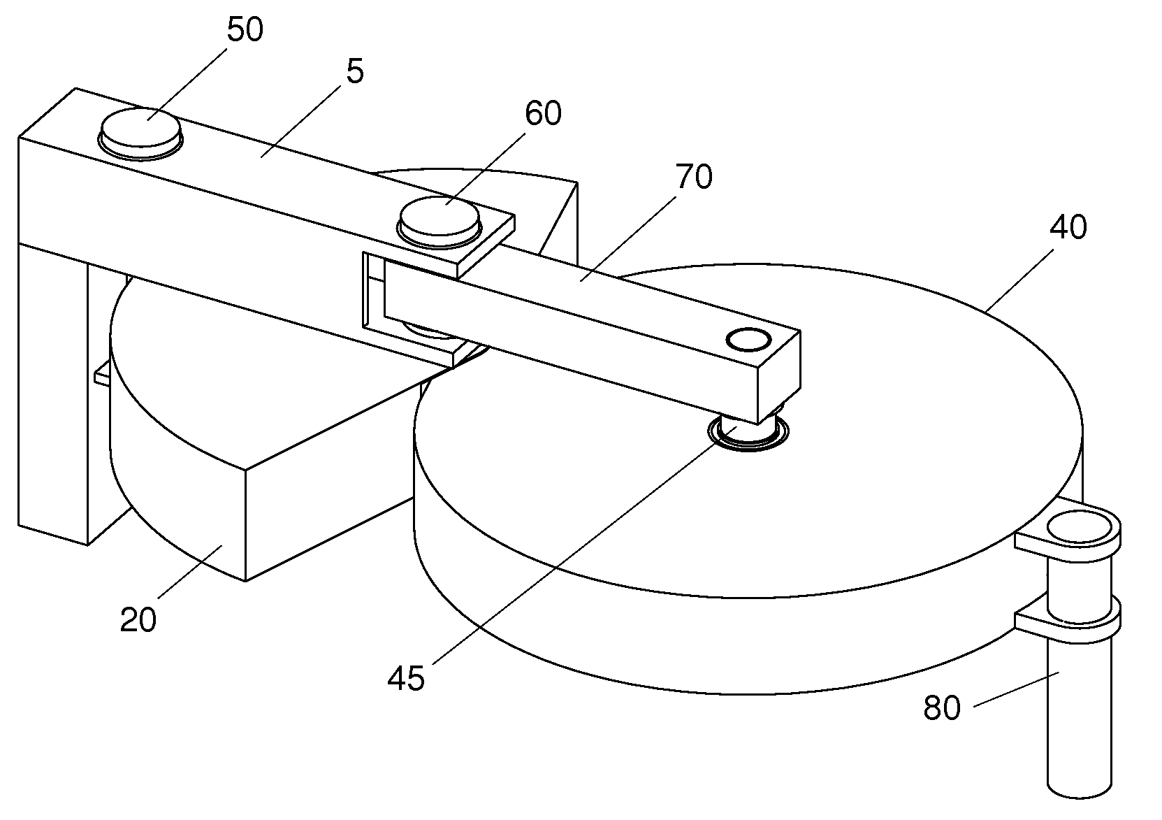
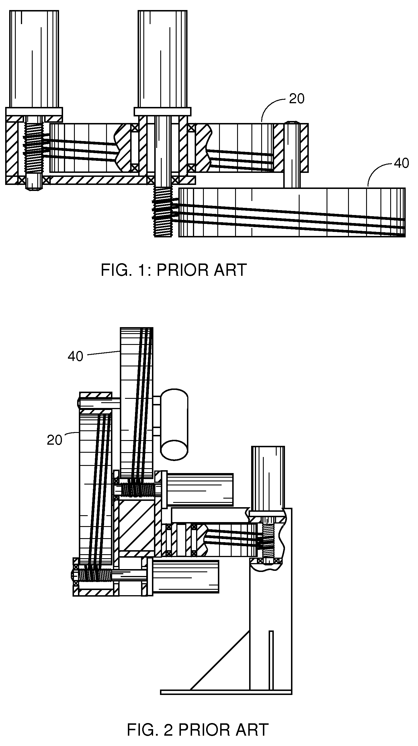
The construction and benefits of a two degree-of-freedom manipulator as shown in FIG. 1 is described in related U.S. Pat. No. 5,429,015. With its scarcity and simplicity of components, this 2 degree-of-freedom mechanism offers high performance and economical construction. The motors do not move relative to the motion of the driven drums, so there is no performance penalty for using large motors to achieve rapid accelerations. No belts, chains, or linkages are required to transmit motor torques to the moving members. No additional transmission reduction mechanism is required. The short mechanical distance from motor to the controlled output point allows higher accelerations, more accurate positioning, and more accurate force and torque than competing designs. This design is well suited for applications that require fast and accurate planar motion, as in a SCARA (selective compliance articulated robot arm) industrial robot.

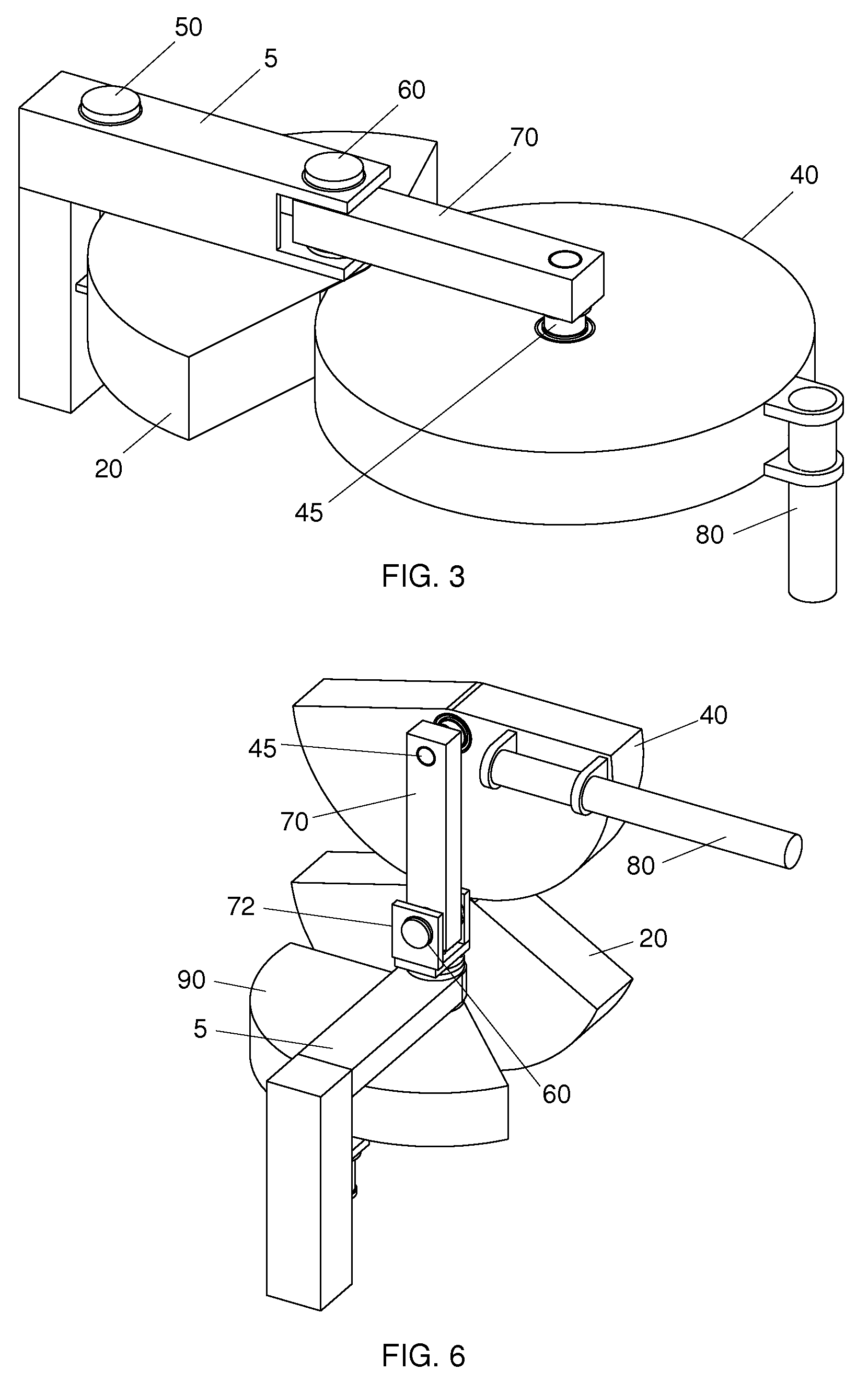
FIGS. 3-5 show a selective compliance articulated robot arm (S...


PUM


Abstract

A two degree-of-freedom positioning and manipulating apparatus is provided. The apparatus includes a first driven member rotatable about a first driven axis, a first driver member coupled to a first driven member for rotating the first driven member about the first driven axis, and a link member fixedly connected to the first driven member. The apparatus further includes a second driven member rotatably mounted to the link member for rotating about a second driven axis, with the second driven axis generally parallel to the first driven axis, and a second driver member coupled at a drive point to the second driven member for rotating the second driven member about the second driven axis. The drive point is generally coincident with the first driven axis.

Description

TECHNICAL FIELD OF THE INVENTIONThe present invention relates to a two (2) degree-of-freedom positioning and manipulating apparatus as well as its extension to three (3) degrees of freedom. More particularly, the present invention relates to both a 2 and 3 degree-of-freedom manipulating apparatus constructed from rotary drives.DESCRIPTION OF THE RELATED ARTU.S. Pat. Nos. 5,429,015 and 5,553,509, the entire disclosures of which are incorporated herein by reference, describe 2 and 3 degree-of-freedom manipulators constructed from rotary drives that realize lower mass, inertia, friction, and joint roughness compared to other designs. FIG. 1. shows the 2 degree-of-freedom configuration as described in the '015 patent. Such configuration features a scarcity of components, as rotary drives of the style employed are easy to fabricate with a minimum of parts. Plus, no auxiliary power transmission components are required to deliver power from the stationary motor to the second link in the se...

Claims


Application Information

Patent Timeline
Patent Type & Authority Patents(United States)
IPC IPC(8): B25J9/12
CPCB25J9/104B25J9/042B25J9/126B25J9/146Y10S901/16
Inventor SOMES, STEVEN D.
Owner SOMES STEVEN D
Why Eureka
Try Eureka