Path protection method and layer-2 switch

a path protection and layer-2 technology, applied in data switching networks, frequency-division multiplexes, instruments, etc., can solve the problems of blocking ports that cannot be used for the purpose of distributing load, requiring higher equipment investment, and difficult to install protocols in current operating networks

Active Publication Date: 2007-04-19
FUJITSU LTD
View PDF7 Cites 50 Cited by
  • Summary
  • Abstract
  • Description
  • Claims
  • Application Information

AI Technical Summary

Benefits of technology

[0027] According to at least one embodiment of the present invention, path protection is achieved by making low equipment investments that only expand the function of end nodes.

Problems solved by technology

When a redundancy protocol such as the spanning tree protocol is used in a bridge network, the following problems may arise.
Because of this, it is extremely difficult to install the protocol in a currently operating network.
Second, layer-2 switches that support a redundancy protocol are generally provided at higher per unit price, thereby requiring higher equipment investment.
Because of this, the blocking ports cannot be used for the purpose of distributing the load.

Method used


Image

  • Path protection method and layer-2 switch
  • Path protection method and layer-2 switch
  • Path protection method and layer-2 switch

Examples


Embodiment Construction

[0046] In the following, embodiments of the present invention will be described with reference to the accompanying drawings.

[0047]

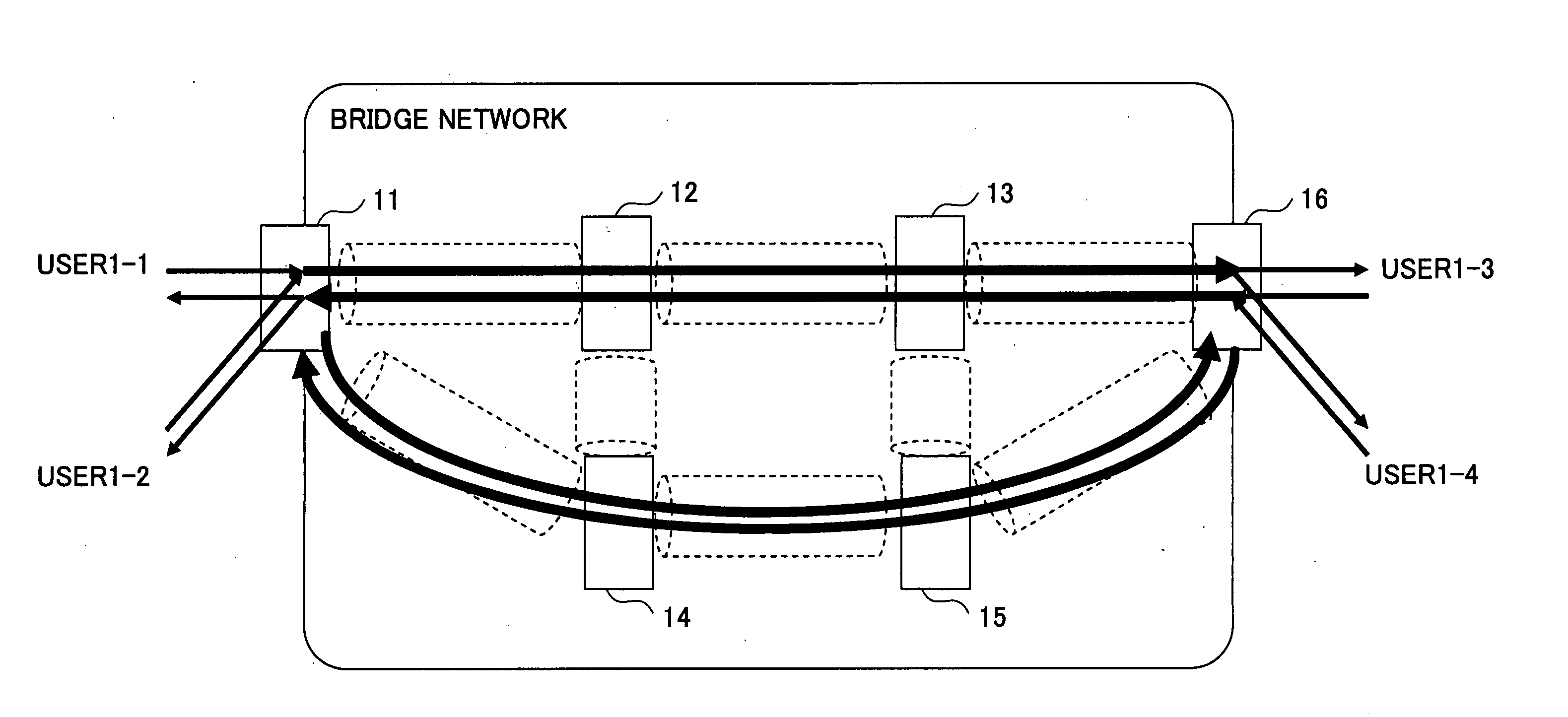
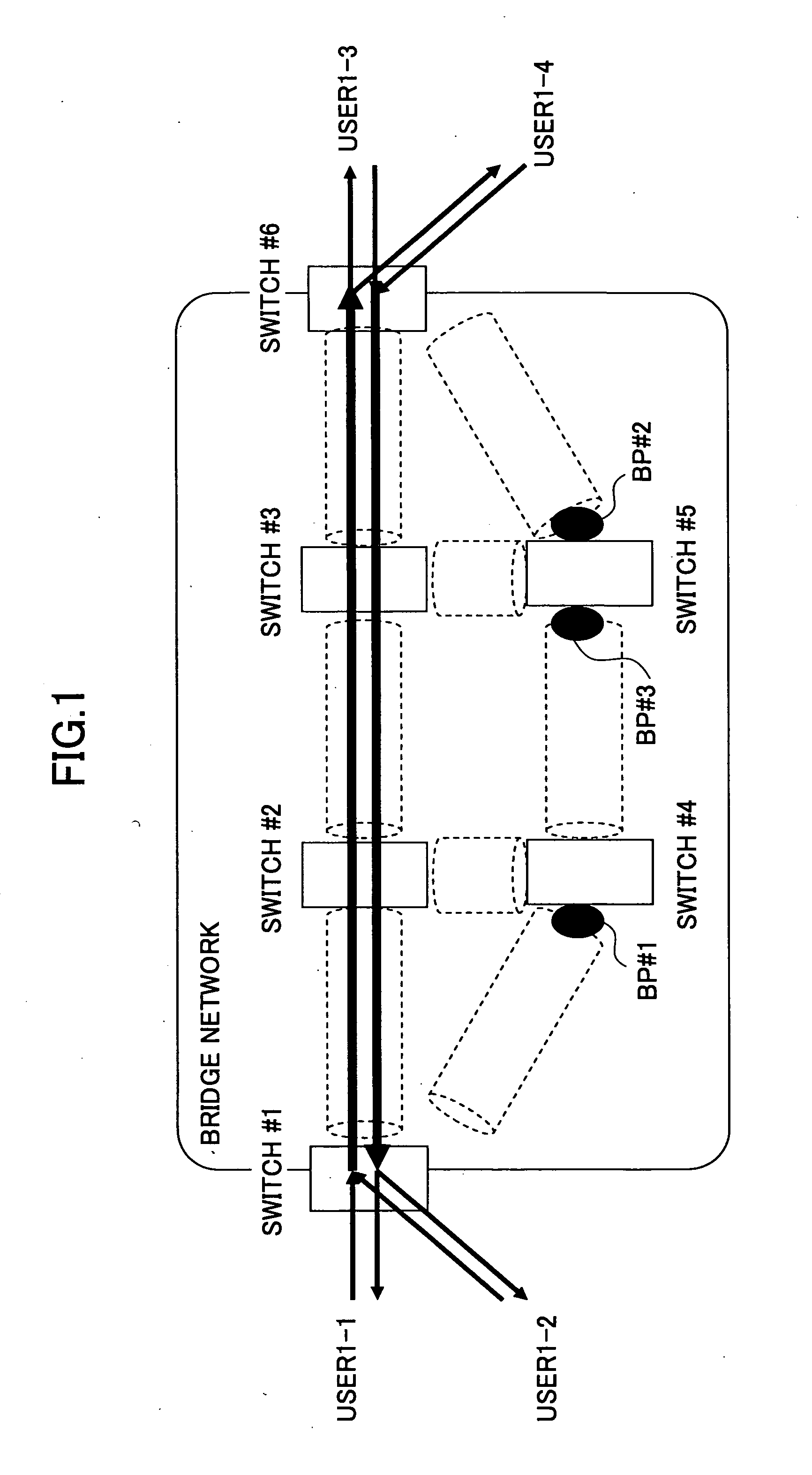
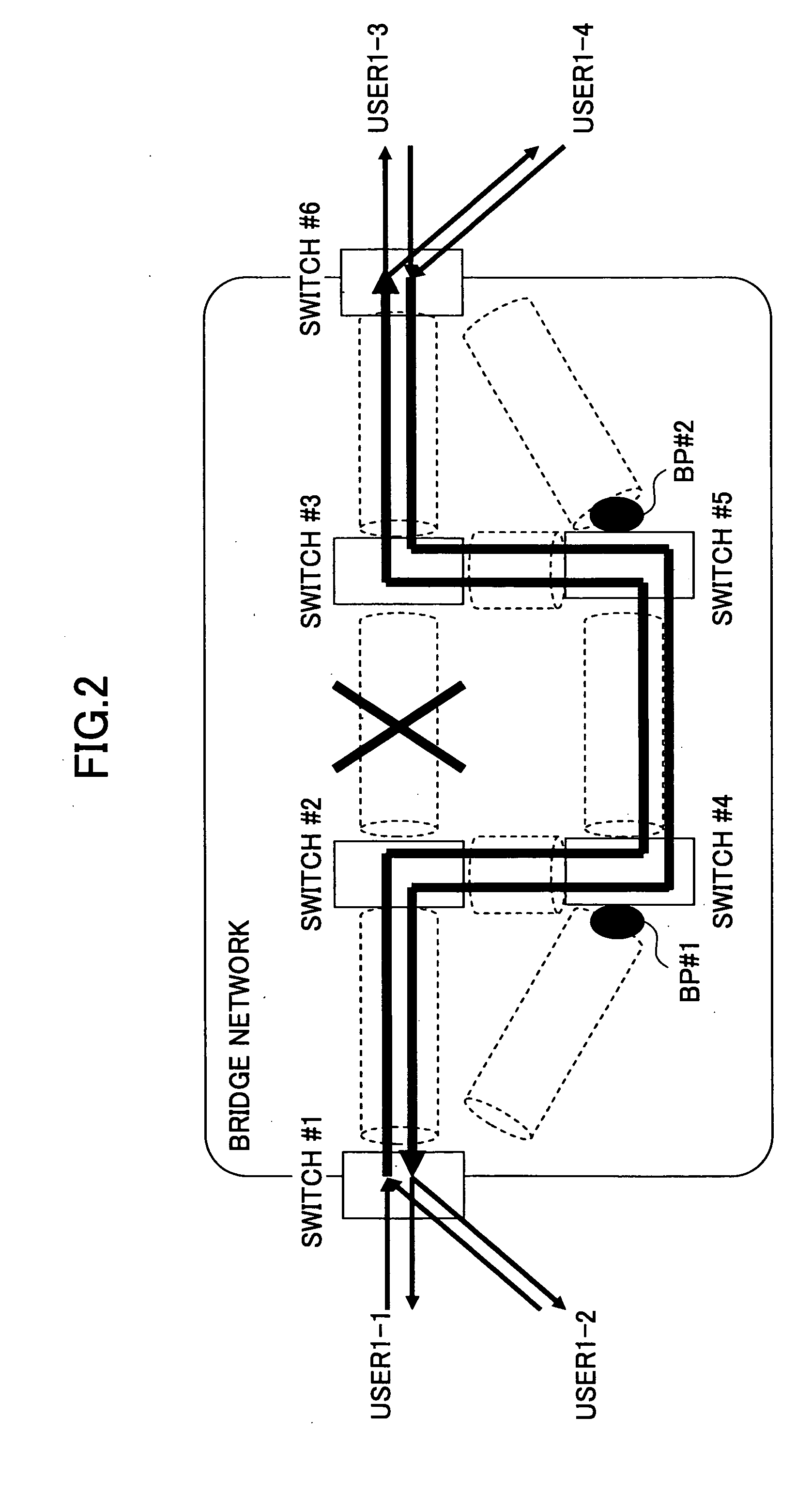
[0048]FIG. 3 is a drawing showing the configuration of an embodiment of a bridge network according to the present invention. In FIG. 3, layer-2 switches 11 through 16 constitute a bridge network. The layer-2 switches 11 and 16 are connected to a user terminal or to a user network that is not controlled from the bridge-network side. The layer-2 switches 11 and 16 are called end nodes because they are located at the ends of the bridge network. The layer-2 switches 12 through 15 have no connection to an external terminal or network. Since the switches 12 through 15 relay traffics passing through the bridge network, these switches are referred to as relay nodes.

[0049] In this embodiment, the end nodes 11 and 16 are coupled to each other through a point-to-point connection. The working path may be the path that passes through the layer-2 switches 11, 12, 13,...


PUM


Abstract

A method of providing path protection includes setting a working path and a protection path by identifying, as a single path, a set of a control-purpose virtual network identifier and at least one virtual network identifier that are assigned to one or more users at a section defined as a point-to-point connection in a virtual network, and switching between the working path and the protection path.

Description

BACKGROUND OF THE INVENTION [0001] 1. Field of the Invention [0002] The present invention generally relates to path protection methods and layer-2 switches, and particularly relates to a path protection method and a layer-2 switch used in a bridge network. [0003] 2. Description of the Related Art [0004] Bridge networks were mainly used in LANs (Local Area Networks) in early days. Since then, their use has been spreading to carrier networks as signified by the fact that the bridge networks are now referred to as “wide-area Ethernet (registered trademark)”. [0005] When bridge networks are used for carrier networks, there is a demand for improvement in fault tolerance with respect to bridge networks, apparatuses constituting the bridge networks, and links between the apparatuses constituting the bridge networks. [0006] To this end, redundancy configuration is employed at various levels, including redundancy in the channel cards of the apparatuses, redundancy in the control cards of the...

Claims


Application Information

Patent Timeline
Patent Type & Authority Applications(United States)
IPC IPC(8): H04J3/14H04L12/46H04L45/24H04L45/247H04L45/50
CPCH04L12/462H04L12/4645H04L45/22H04L45/28H04L45/48H04L49/354H04L49/552H04L43/0811
Inventor DOUKAI, MASAMITAKATORI, KOKAWARAI, KENICHI
Owner FUJITSU LTD
Why Eureka
Try Eureka