Radiation imaging apparatus and table therefor

Inactive Publication Date: 2007-04-19
CANON KK
View PDF23 Cites 28 Cited by
  • Summary
  • Abstract
  • Description
  • Claims
  • Application Information

AI Technical Summary

Benefits of technology

[0023] The present invention is directed to a radiation imaging apparatus and a table for the apparatus that are capable of performing an effective photographing operation by moving a tabletop in a widthwise and lengthwise directions.

Problems solved by technology

However, it is difficult to cover the entire extremity of the patient including the head and the leg.
In addition, in the method by which both the tabletop 3 and the radiation imaging unit 4 are moved, working performance is low, and an effective photographing operation cannot be performed.
Accordingly, a force required for moving at the time of operation by the radiologist, and a sway of the imaging table at the time of stopping the moving operation increase, and thus operability can deteriorate.
Especially, the sway that occurs at the time of stopping the movement in the widthwise direction, causes also the body of the patient to sway so that the patient feels unnecessary pain.
In this case, the radiologist is required to deliberately perform the operation while confirming the surrounding state, and thus the operability deteriorates.

Method used


Image

  • Radiation imaging apparatus and table therefor
  • Radiation imaging apparatus and table therefor
  • Radiation imaging apparatus and table therefor

Examples


first embodiment

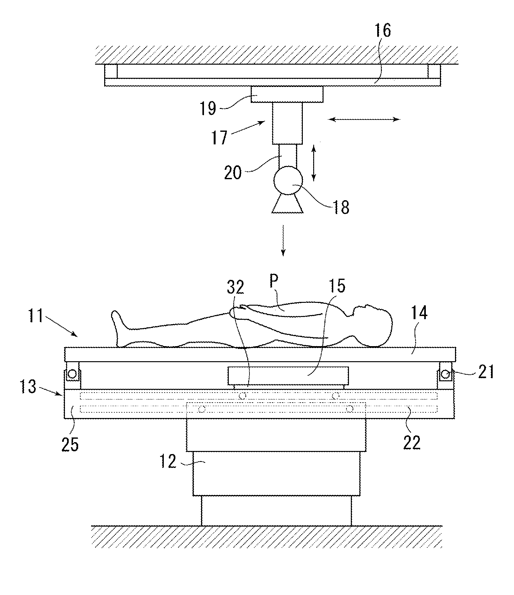
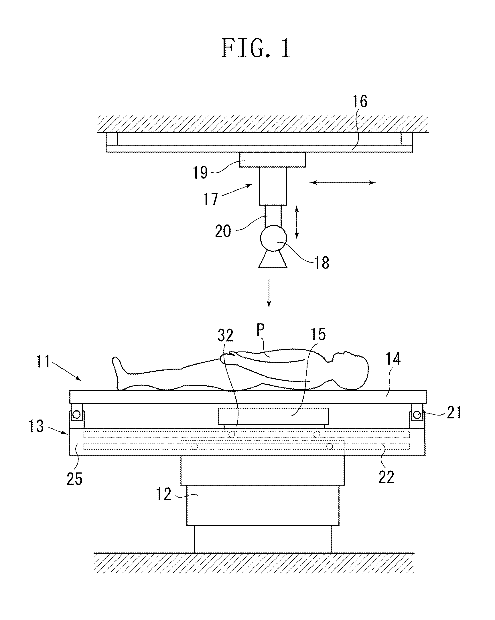
[0039]FIG. 1 is a diagram that illustrates a configuration of a radiation imaging apparatus according to a first embodiment of the present invention seen from a longer side of a tabletop. A table 11 is fixed onto a floor of an imaging chamber. The table 11 is provided with a tabletop moving mechanism unit 13 via a base unit 12. A tabletop 14 onto which a patient P lays down, can move in a horizontal plane and is placed onto the tabletop moving mechanism unit 13. A radiation imaging unit 15 contains an X-ray image detection device. The X-ray image detection device detects X-rays that is transmitted through the patient P, and is disposed on the tabletop moving mechanism unit 13.

[0040] A tube supporting mechanism 17 and an X-ray tube 18 are provided above the table 11. The tube supporting mechanism 17 is suspended via a rail 16 provided to a ceiling of the imaging chamber, and the X-ray tube 18 is installed to a lower portion of the tube supporting mechanism 17. The tube supporting me...

second embodiment

[0054]FIG. 5 is a diagram that illustrates a mechanism for electrically moving the radiation imaging unit 15 which is added as a component necessary for the alignment to the basic configuration of the first embodiment. The same components as the first embodiment are provided with the same numerals and symbols. At both ends of the frame 25, a widthwise locking mechanism 41 that fixes the movement of the tabletop 14 in the widthwise direction is provided. In the same way, the base unit 12 is provided with a lengthwise locking mechanism 42 that fixes the movement of the frame 25 in the lengthwise direction. The locking mechanisms 41 and 42 respectively include an electromagnet, and are capable of inhibiting free movement of the tabletop 14 while the electromagnet fixes the tabletop 14 to the frame 25 by the absorption effect. The operation of the locking is performed by a controller 43, and the releasing operation of the locking is performed by a foot switch 44 provided to the side of ...

third embodiment

[0063]FIG. 6 is a diagram that illustrates a third embodiment of the present invention, in which the movement of the radiation imaging unit 15 is performed manually. The components that are provided with the same numerals and symbols as the example shown in FIG. 5 have the same function as in FIG. 5, and accordingly, the explanation thereof is not repeated. In the third embodiment, the drive unit 45, driven pulleys 48 and 49, and the timing belt 50 are unnecessary, and a switch 61 for releasing the imaging unit locking mechanism 52 and a handle 62 for moving the radiation imaging unit 15 are provided. The switch 61 is turned on when the radiologist grips a circumference of the moving handle 62. Accordingly, the lock can be released without pressing the switch 61 by the radiologist at the time of moving, and thus a good operability can be achieved.

[0064] Upon detection of a signal indicating that the switch 61 is turned on, the controller 43 releases the locking of the imaging unit ...


PUM


Abstract

A radiation imaging apparatus including a tabletop onto which a patient lays down, a radiation imaging unit positioned below the tabletop and configured to detect radiation that transmits through the patient, a widthwise moving member supporting the tabletop and configured to move the tabletop in a widthwise direction, a moving mechanism unit including a lengthwise moving mechanism configured to move the tabletop in a lengthwise direction, the moving mechanism unit supporting the widthwise moving member and supporting the radiation imaging unit so as to be movable in the lengthwise direction, and a base unit supporting the moving mechanism unit.

Description

BACKGROUND OF THE INVENTION [0001] 1. Field of the Invention [0002] The present invention relates to a radiation imaging apparatus that projects radiation such as X-ray to a patient (subject) who is laying down on a tabletop of a table and a bed, and photographs with the radiation that transmits through the patient using a radiation imaging unit disposed below the tabletop, and also relates to a table for the radiation imaging apparatus. [0003] 2. Description of the Related Art [0004] Conventionally, radiation imaging apparatuses are used in various fields such as in nondestructive inspection of a material. In this kind of radiation imaging apparatus, a so-called radiography is utilized in which an intensifying screen and a radiographic film are brought into close contact with each other. In the radiation imaging apparatus, when the radiation that transmits through the patient is incident on the intensifying screen, a phosphor included in the intensifying screen absorbs energy from ...

Claims


Application Information

Patent Timeline
IPC IPC(8): H05G1/02
CPCA61B6/0457A61B6/4464A61B6/0487
Inventor KOBAYASHI, MASAAKI
Owner CANON KK
Why Eureka
Try Eureka